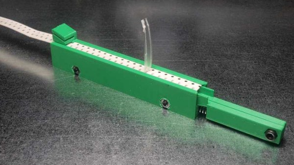
Every so often, a project is worth some extra work to see if the idea can go any further. [JohnSL] has been busy doing exactly that with his spring-loaded SMT tape holder project. Having done the original with 3D printing, he has been working on designing for injection molding. This isn’t a motorized feeder, it’s still a manual tool but it is an improvement over the usual workshop expedient method of just sticking segments of tape down to the desktop. Tape is fed into the holders from one end and spring tension holds the tape firm while a small slot allows the cover tape to be guided backward after peeling. As anyone who has used cut segments of tape to manually deal with SMT parts knows, small vibrations — like those that come from peeling off the clear cover — can cause the smaller components to jump around and out of their pockets, and any length of peeled cover gets awkward quickly.
In [JohnSL]’s design, all SMT tapes sit at an even height regardless of size or tape thickness. A central support pushes up from the bottom with tension coming from a spring pulling sideways; the central support is forced upward by cams and presses against the bottom surface of the tape. As a result, the SMT tape gets supported from below with even tension and the whole assembly maintains a narrow profile suitable for stacking multiple holders side by side. The CAD files are available online along with a McMaster-Carr part number for the specific spring he used.
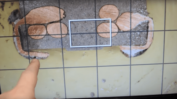
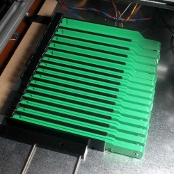
After working out the kinks on 3D printed prototypes, [JohnSL] decided to see if it would be feasible to design an injection molded version and made a video outlining the process, embedded below.
Continue reading “Make A Better, Spring-Loaded SMT Tape Strip Holder”