The Battery Is Part Of The Art

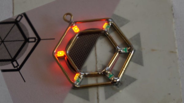
A work of art is appreciated for its own sake and we will never tire of seeing stunning circuits from microscopic dead-bugs to ornate brass sculptures. We also adore projects that share the tricks to use in our own work. Such is the case with [Jiří Praus] who made some jewelry and shared his templates so we try this out ourselves.

The materials include brass wire, solder, and surface-mount LEDs. Template design expects a 1206 light, so if you step outside that footprint, plan accordingly. The printable templates are intuitive and leverage basic wire jewelry making skills. Some good news is that flashing LEDs are available in that size so you can have an array of blinkenlights that appears random due to drifting circuits. Please be wary with RGB lights or mixing colors because red LEDs generally run at a lower voltage and they will siphon a significant chunk of a coin-cell’s power from a competing green or blue. How else can these be personalized?

[Jiří]’s charms are just the latest of circuits that capture our eyes and tickle our ears.

Dead Bug Arduino Is Lively And Shield-Compatible

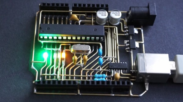
Microcontroller demo boards such as the Arduino UNO are ubiquitous on Hackaday as the brains of many a project which inevitably does something impressive or unusual. Sometime someone builds a particularly tiny demo board, or an impressively large one. In the case of the board featured here, the Arduino is a gorgeous labor of love which can’t really be called a board since there is no PCB. Instead of the traditional fiberglass, [Jiří Praus] formed brass bars into the circuitry and held it together with solder.

This kind of dedication to a project leaves an impression. His notes show he saw the barest way to operate an ATMega328, built it, tested, and moved on to the power supply to make it self-sustaining, then onto the communication circuit, and finally the lights. The video below shows a fully-functional Arduino happily running the blink program. He plans to encase the brass portion in resin to toughen it up and presumably keep every bump from causing a short circuit. The components are in the same position due to a custom jig which means a standard shield will fit right into place.

The Arduino started far less flashy yet nearly as fragile, and it has grown. And shrunk.

Continue reading “Dead Bug Arduino Is Lively And Shield-Compatible”

Ask Hackaday: Get The Lead Out Or Not?

For most of the history of industrial electronics, solder has been pretty boring. Mix some lead with a little tin, figure out how to wrap it around a thread of rosin, and that’s pretty much it. Sure, flux formulations changed a bit, the ratio of lead to tin was tweaked for certain applications, and sometimes manufacturers would add something exotic like a little silver. But solder was pretty mundane stuff.

Source: RoHS Guide

Then in 2003, the dull gray world of solder got turned on its head when the European Union adopted a directive called Restriction of Hazardous Substances, or RoHS. We’ve all seen the little RoHS logos on electronics gear, and while the directive covers ten substances including mercury, cadmium, and hexavalent chromium, it has been most commonly associated with lead solder. RoHS, intended in part to reduce the toxicity of an electronic waste stream that amounts to something like 50 million tons a year worldwide, marked the end of the 60:40 alloy’s reign as the king of electrical connections, at least for any products intended for the European market, when it went into effect in 2006.

Continue reading “Ask Hackaday: Get The Lead Out Or Not?”

Recover Data From Damaged Chips

Not every computer is a performance gaming rig. Some of us need cheap laptops and tablets for simple Internet browsing or word processing, and we don’t need to shell out thousands of dollars just for that. With a cheaper price tag comes cheaper hardware, though, such as the eMMC standard which allows flash memory to be used in a more cost-advantageous way than SSDs. For a look at some the finer points of eMMC chips, we’ll turn to [Jason]’s latest project.

[Jason] had a few damaged eMMC storage chips and wanted to try to repair them. The most common failure mode for his chips is “cratering” which is a type of damage to the solder that holds them to their PCBs. With so many pins in such a small area, and with small pins themselves, often traditional soldering methods won’t work. The method that [Jason] found which works the best is using 0.15 mm thick glass strips to aid in the reflow process and get the solder to stick back to the chip again.

Doing work like this can get frustrating due to the small sizes involved and the amount of heat needed to get the solder to behave properly. For example, upgrading the memory chip in an iPhone took an expert solderer numerous tries with practice hardware to finally get enough courage to attempt this soldering on his own phone. With enough practice, the right tools, and a steady hand, though, these types of projects are definitely within reach.

Bottom Of The Barrel Connector: Tell Us Your Socket Hacks

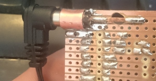
Sometimes you get an epiphany for a project that will change the world. A simple device, on a custom circuit board with inexpensive parts that will disrupt the status quo and make you a billion dollars in no time. Then there are the times where you need to throw scraps of copper at a prototyping board and strangle nine-volts out by any means necessary.

This is about the latter. In one of our Hack Chats, [Morning.Star] shared a couple of images wherein a barrel connector was needed, but there was no time to wait for one in the mail. Necessity birthed the most straightforward solution which did not involve shredding a power adapter’s plug. There is no link, [Stuart Longland] aka [Redhatter] screen-capped the image exchange and reminded us on the tip line.

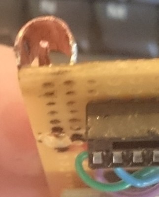
Chances are you’ve faced this problem yourself. Everyone has a box of old wall warts somewhere, exhibiting a wide range of barrel connector sizes. If you can’t take the easy route of cutting off the connectors, what’s your go-to trick? Alligator clips are a horrid approach, and there aren’t really any clear winners that come to mind. [Morning.Star’s] hack is actually quite respectable! It appears to be a roll of copper (perhaps from tubing?) bent for a bit of spring tension on the outside of the barrel. The inside is contacted by thick copper wire with a kink to again provide spring action.

So, spill the beans. What’s your barrel connector trick and does it work reliably?

The Modern Analog Soldering Station

There is a certain sense of accomplishment one gets when building their own tools. This is what [Alejandro Velazquez] was going for when he built his own soldering station. Sure you can get a decent station for a pittance on Amazon, or eBay. You can even build your own microprocessor controlled station. [Alejandro] is currently interested in analog electronics, so he went that route to build his own closed-loop station.

The handle is a 50 watt, 24-volt affair with a thermocouple. You can find this handle on many Hakko 907 clone soldering stations, often referred to as the 907A. The station itself is completely analog. A triac switches the current going to the heater. The triac is controlled by a PWM signal. The PWM itself is generated and regulated by an LM324 quad op-amp, which is the heart of the station. The op-amp compares the setpoint with the current temperature read from the soldering handle’s thermocouple, then adjusts the duty cycle of the PWM signal to raise, or lower the temperature.

It’s a classic control system, and the schematic is definitely worth checking out if you want to understand how op-amps can be used to create complex operations.

You can find plenty more information on analog electronics right here on Hackaday — we’ve covered thermocouple amplifiers, as well as instrumentation amps. If you’re more of a digital man, check out this Arduino controlled soldering station!

Seeing A Webcam’s PCBs In A Whole Different Light

When it comes to inspection of printed circuits, most of us rely on the Mark I eyeball to see how we did with the soldering iron or reflow oven. And even when we need the help of some kind of microscope, our inspections are still firmly in the visible part of the electromagnetic spectrum. Pushing the frequency up a few orders of magnitude and inspecting PCBs with X-rays is a thing, though, and can reveal so much more than what the eye can see.

Unlike most of us, [Tom Anderson] has access to X-ray inspection equipment in the course of his business, so it seemed natural to do an X-ray enhanced teardown and PCB inspection. The victim for this exercise was nothing special – just a cheap WiFi camera of the kind that seems intent on reporting back to China on a regular basis. The guts are pretty much what you’d expect: a processor board, a board for the camera, and an accessory board for a microphone and IR LEDs. In the optical part of the spectrum they look pretty decent, with just some extra flux and a few solder blobs left behind. But under X-ray, the same board showed more serious problems, like vias and through-holes with insufficient solder. Such defects would be difficult to pick up in optical inspection, and it’s fascinating to see the internal structure of both the board and the components, especially the BGA chips.

If you’re stuck doing your inspections the old-fashioned way, fear not – we have tips aplenty for optical inspection. But don’t let that stop you from trying X-ray inspection; start with this tiny DIY X-ray tube and work your way up from there.

Thanks for the tip, [Jarrett].