Optimizing AVR LCD Libraries

A while ago, [Paul Stoffregen], the creator of the Teensy family of microcontrollers dug into the most popular Arduino library for driving TFT LCDs. The Teensy isn’t an Arduino – it’s much faster – but [Paul]’s library does everything more efficiently.

Even when using a standard Arduino, there are still speed and efficiency gains to be made when driving a TFT. [Xark] recently released his re-mix of the Adafruit GFX library and LCD drivers. It’s several times faster than the Adafruit library, so just in case you haven’t moved on the Teensy platform yet, this is the way to use one of these repurposed cell phone displays.

After reading about [Paul]’s experience with improving the TFT library for the Teensy, [Xark] grabbed an Arduino, an LCD, and an Open Workbench Logic Sniffer to see where the inefficiencies in the Adafruit library were. These displays are driven via SPI, where the clock signal goes low for every byte shifted out over the data line. With the Adafruit library, there was a lot of wasted time in between each clock signal, and with the right code the performance could be improved dramatically.

The writeup on how [Xark] improved the code for these displays is fantastic, and the results are impressive; he can fill a screen with pixels at about 13FPS, making games that don’t redraw too much of the screen at any one time a real possibility.

Simple Keypad Scanning With SPI And Some Hardware

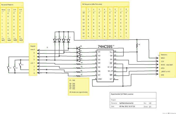
16-button keypads have a clever method of encoding their data into 8 pins. Pins are mapped to four rows and four columns on the keypad. A user reads the keypad by bringing each row up to logic: HIGH, and reading the corresponding column values, (HIGH or LOW). Keypad scanning can be farmed out to a microcontroller with a simple finite-state machine and some button debouncing techniques. [Mario], [Glen], and [Paul] on the Netduino forums took an entirely different route: they’ve designed and implemented a Keypad Scanner using any microcontrollers SPI peripheral and a 74HC595 Shift register.

The trio’s solution is an elegant adventure into circuit design. With two diodes and a voltage divider, they devise a simple circuit that pulls the SPI MISO line LOW if a button in the corresponding circuit’s row is pushed closed. Copied four-fold, this circuit joins the rows and columns of the 74HC595 to the keypad matrix. To scan across the four columns, the microcontroller performs an SPI transfer of the key value: 0x01. To decode which button is pushed, the value received back from the SPI bus encodes which button was pushed out of the 16 possible buttons. Note: some cases for ambiguity as to “which button was pressed” do exist if multiple buttons are pushed at the same time, but for the general case where we’re punching in values one-by-one, this circuit works perfectly.

The team’s hack is a clever use of existing hardware to outsource a microcontroller’s software problem to hardware while leveraging the SPI peripheral to cleverly decrypt and retrieve data back from the keypad. Kudos to the team of three over at the Netduino Forums, and we’re always thrilled to see and idea grow from one person to the next. In case you want to take a step lower and build up the keypad itself, here’s a blast from the past that does just that.

High Speed SSD1306 Library

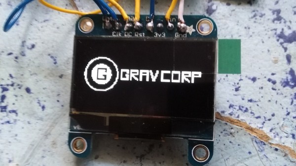
[Lewin] wrote in to tell us about a high speed library for Arduino Due that he helped develop which allows interfacing OLED displays that use the SSD1306 display controller, using DMA routines for faster display refresh time.

Typically, displays such as the Monochrome 1.3″ 128×64 OLED graphic display , are interfaced with an Arduino board via the SPI or I2C bus. The Adafruit_SSD1306 library written by [Limor Fried] makes it simple to use these displays with a variety of Arduinos, using either software or hardware SPI. With standard settings using hardware SPI, calls to display() take about 2ms on the Due.

[Lewin] wanted to make it faster, and the SAM3X8E on the Due seemed like it could deliver. He first did a search to find out if this was already done, but came up blank. He did find [Marek Buriak]’s library for ILI9341-based TFT screens. [Marek] used code from [William Greiman], who developed SD card libraries for the Arduino. [William] had taken advantage of the SAM3X8E’s DMA capabilities to enable faster SD card transfers, and [Marek] then adapted this code to allow faster writes to ILI9341-based screens. All [Lewin] had to do was to find the code that sent a buffer out over SPI using DMA in Marek’s code, and adapt that to the Adafruit library for the SSD1306.

There is a caveat though: using this library will likely cause trouble if you are also using SPI to interface to other hardware, since the regular SPI.h library will no longer work in tandem with [Lewin]’s library. He offers some tips on how to overcome these issues, and would welcome any feedback or testing to help improve the code. The speed improvement is substantial. Up to 4 times quicker using standard SPI clock, or 8 times if you increase SPI clock speed. The code is available on his Github repo.

Using I2C Addresses As Chip Selects

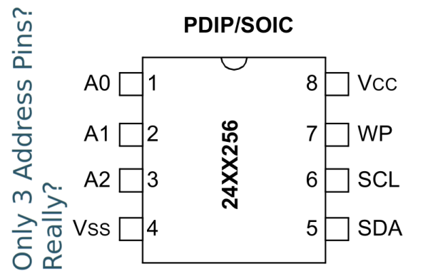
I2C has a seven-bit address space, and you’re thinking “when do I ever need more than 127 devices on a pair of wires?” So you order up some parts only to find that they have one, two, or three user-configurable address pins for any given device type. And you need a bunch more than four or eight capacitive sensor buttons on your project. What do you do?

If you’re reader [Marv G], you think outside the box and realize that you can change the addresses on the fly by toggling address pins high and low with your microcontroller. That is, you can use a single I2C address pin for each device as a chip select signal just like you would have with SPI.

That’s it, really. [Marv G] goes through all of the other possible options in his writeup, and they’re all unsavory: multiple I2C busses, a multiplexer, buying different sensors, or changing micros. None of these are as straightforward as just running some more wires and toggling these with your micro.

We’d even go so far as to suggest that you could fan these chip select lines out with a shift register or one of those 1-of-N decoder chips, depending on how many I2C devices you need to chip-selectify. (We’re thinking 74HC595 or 74HC154.)

Along the way, we found this nice list of the number of address pins for a bunch of common peripherals provided by [LadyAda], in case you don’t believe us about how ubiquitous this problem is. How many devices on that list have one (1!!) address pin?

At the end of his post, [Marv G] asks if anyone else has thought of this chip select trick before. We hadn’t. Here’s your chance to play the smart-ass in the comments.

New Part Day: SPI RAM And A Video Controller

Generating video signals with a microcontroller or old CPU is hard if you haven’t noticed. If you’re driving even a simple NTSC or PAL display at one bit per pixel, you’re looking at a minimum of around 64kB of RAM being used as a frame buffer. Most microcontrollers don’t have this much RAM on the chip, and the AVR video builds we’ve seen either have terrible color or relatively low resolution.

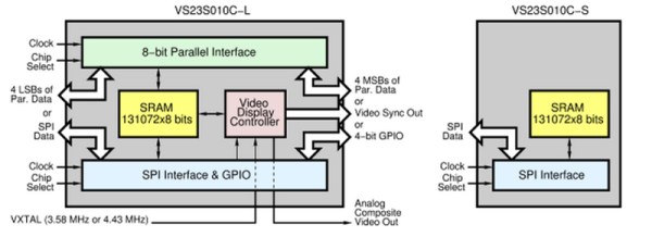
Here’s something interesting that solves the memory problem and also generates analog video signals. Yes, such a chip exists, and apparently this has been in the works for a very long time. It’s the VLSI VS23s010C-L, and it has 131,072 bytes of SRAM and a video display controller that supports NTSC and PAL output.

There are two chips in the family, one being an LQFP48 package, the other a tiny SMD 8-pin package. From what I can tell from the datasheets, the 8-pin version is only an SPI-based SRAM chip. The larger LQFP package is where the action is, with parallel and SPI interfaces to the memory, an input for the colorburst crystal, and composite video and sync out.

After looking at the datasheet (PDF), it looks like generating video with this chip is simply a matter of connecting an RCA jack, throwing a few commands to the chip over SPI, and pushing bits into the SRAM. That’s it. You’re not getting hardware acceleration, you’re going to have to draw everything pixel by pixel, but this looks like the easiest way to generate relatively high-resolution video with a single part.

Thanks [antibyte] for the tip on this one.

Controlling Analog with SPI

We Assume Control: SPI And A Digital Potentiometer

In the last video I demonstrated a Universal Active Filter that I could adjust with a dual-gang potentiometer, here I replace the potentiometer with a processor controlled solid-state potentiometer. For those that are too young to remember, we used to say “solid-state” to differentiate between that and something that used vacuum tubes… mostly we meant you could drop it without it breakage.

The most common way to control the everyday peripheral chips available is through use of one of the common Serial Protocols such as I2C and SPI.  In the before-time back when we had only 8 bits and were lucky if 7 of them worked, we used to have to memory map a peripheral or Input/Output (I/O) controller which means we had to take many control and data lines from the microprocessor such as Data, Address, Read/Write, system clocks and several other signals just to write to a couple of control registers buried in a chip.

Nowadays there is a proliferation of microcontrollers that tend to have built-in serial interface capability it is pretty straightforward to control a full range of peripheral functions; digital and analog alike.  Rather than map each peripheral using said data and address lines,which is a very parallel approach,  the controller communicates with peripherals serially using but a handful of signal lines such as serial data and clock. A major task of old system design, mapping of I/O and peripherals, is no longer needed.

Continue reading “We Assume Control: SPI And A Digital Potentiometer”

Everyone’s Favorite Energy Meter Hack, Now Wireless

[Kalle] is at it again with more hacks on electricity use meters. This time, the meter has been hacked to stream their data over the aether wirelessly. Now, data can be grabbed from multiple devices simultaneously, making the possibilities for home energy monitoring limitless

The first project [Kalle] did involved finding a meter from China with capabilities similar to (and cheaper than) the Kill-a-Watt meters. Unlike the Kill-a-Watt which spits out analog values, the Chinese meter sent digital information out on a ribbon cable with the bus lines labeled. Since the meter was so hackable, [Kalle] took it even further in this hack.

With those pesky wires out of the way, the device now uses an Arduino Pro Mini to sniff the energy meter’s data stream. Then it transmits the data wirelessly with a nRF34L01+ transceiver. As a perk, all of these chips fit inside the case of the energy meter, making this a very tidy hack indeed. The project code an incredible amount of detail is available on the project site, so be sure to check this one out for all of your energy monitoring needs!