If you’ve done even the most cursory research into buying a laser cutter, you’ve certainly heard of the K40. Usually selling for around $400 USD online, the K40 is not so much a single machine as a class of very similar 40 watt CO2 lasers from various Chinese manufacturers. As you might expect, it takes considerable corner cutting to drive the cost down that low, but the K40 is still arguably the most cost-effective way to get a “real” laser cutter into your shop. If you’re willing to do some modifications on the thing, even better.
 One of the shortcomings of the K40 is that it lacks a Z axis, and with thick material that needs multiple cuts at increasingly deeper depths, this can be a hassle. [Aaron Peterson] decided to take it upon himself to design and build an adjustable Z table for the K40 at his local makerspace (River City Labs), and being the swell guy that he is, has made it available under an open source license so the rest of the K40-owning world can benefit from his work.
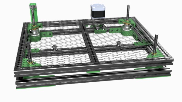
[Aaron] started the design with a number of goals which really helped elevate the project from a one-off hack to a sustainable community project. For one, he only wanted to use easily available commodity hardware to keep the cost down. The most complex components should all be 3D printable so the design would be easy to replicate by others, and finally, he wanted the user to have the ability to scale it in all dimensions. The end result is a electronically controlled lifting platform that anyone can build, for any laser cutter. It doesn’t even have to be limited to laser cutters; if you have a need for precisely raising or lowering something, this design might be exactly what you’re looking for.
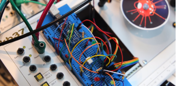
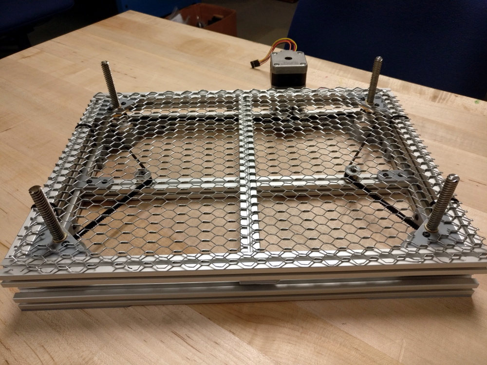
The table is primarily constructed out of 15×15 aluminum extrusion, and uses standard hardware store expanded wire mesh as a top surface. Height is adjusted by rotating the four 95 mm T8 leadscrews with a GT2 belt and pulleys, which prevents any corner from getting out of sync with the others. Connected to a standard NEMA 17 stepper motor, this arrangement should easily be capable of sub-millimeter accuracy. It looks as though [Aaron] has left controlling the stepper motor as an exercise for the reader, but an Arduino with a CNC shield would likely be the easiest route.
We’ve seen a lot of hacking around the K40 over the last couple of years, from spring loaded beds to complete rebuilds which are hardly recognizable. If you’re looking for a cheap laser with a huge catalog of possible hacks and modifications, you could do a lot worse than starting with this inexpensive Chinese machine.