An Affordable And Programmable PLC

We’re all used to general purpose microcontroller boards such as the Arduino or its many imitators, but perhaps we don’t see as much of their industrial cousins. A programmable logic controller (PLC) is a computer designed to automate industrial machinery, and comes with protected interfaces and usually a specific PLC programming environment. Thus [Galopago]’s work with an inexpensive Chinese PLC clone is especially interesting, providing a route forward to using it within the Arduino IDE ecosystem.

Opening it up, the processor is identified as an STM32F103, and the connection needed to place it in bootloader mode is identified. Then it can be programmed from the Arduino IDE, even though its bootloader can’t be changed. Then to complete the process it’s necessary to identify the various different inputs and outputs by old-fashioned hardware reverse engineering.

This PLC may not be quite as robust as some products costing much more money, but it still represents a cost-effective way to access a microcontroller board with much of the interface circuitry already installed that would normally be required for controlling machinery. We expect that we’ll be seeing it appear on these pages over the coming months, and perhaps there might even be another comparison in the air.

Small Open Source Vehicle Hacking Platform

[Florian] and his engineering team at Munich-based bmc::labs has developed a clever set of prototyping boards for vehicle hacking and rapid product development, collectively called the bmc::board or bmc::mini. These stackable development boards were initially designed for in-house use. The team took a general purpose approach to the design so the boards could be used across a wide range of projects, and they should be useful to anyone in the field. [Florian] decided to release the boards to the community as open-source and certified by OSHWA (Open Source Hardware Association).

There are four boards currently defined, with several more in the works:

  • mini::base — Main microcontroller board, STM32F103-based
  • mini::out — I/O board with CAN bus, JTAG, etc.
  • mini:: grid — RF board providing GPS and GSM capability
  • mini::pit — local wireless connectivity, WiFi and Bluetooth, and 2nd CAN bus

At 54 x 42.5 mm, these boards are pretty small; a form-factor they describe as “exactly half a credit card”. We like the Wurth WR-MM family of stacking connectors they are using, and the symmetrical pinout means you can rotate the cards as needed. But at first glance, these thru-hole connectors seem to limit the stack to just two boards, although maybe they plan move to an SMT flavor of the connector in future designs permitting taller stacks.

If you’re into vehicle electronics and/or vehicle hacking, definitely take a look at these. You can check out [Florian]’s bmc::board Hackaday.io project page and the team’s GitHub repository for more details. Here’s another project by team member [Sebastian] using one of the future bmc::bike modules to eavesdrop on ECU communications, where he sensibly advises the reader “First, pull over and get off the bike. Never hack a two-wheeled vehicle while riding it!”.

No discussion of vehicle CAN bus tools should omit the work of Craig Smith, who literally wrote the book on hacking your car, and whose talk along with Hackaday’s own Eric Evenchick of CANtact fame we covered back in 2016. [Florian] has started a CrowdSupply campaign where you can see some more details of this project and a short promotional video.

Teardown: Orthofix SpinalStim

If you’ve ever had a particularly nasty fracture, your doctor may have prescribed the use of an electronic bone growth stimulator. These wearable devices produce a pulsed electromagnetic field (PEMF) around the bone, which has been shown to speed up the natural healing process in a statistically significant number of patients. That’s not to say there isn’t a debate about how effective they actually are, but studies haven’t shown any downsides to the therapy, so it’s worth trying at least.

Image from SpinalStim manual.

When you receive one of these devices, it will be programmed to only operate for a certain amount of time or number of sessions. Once you’ve “used up” the bone stimulator, it’s functionally worthless. As you might imagine, there’s no technical reason this has to be the case. The cynic would say the only reason these devices have an expiration date on them is because the manufacturer wants to keep them from hitting the second hand market, but such a debate is perhaps outside the scope of these pages.

The Orthofix SpinalStim you’re seeing here was given to me by a friend after their doctor said the therapy could be cut short. This provided a somewhat rare opportunity to observe the device before it deactivated itself, which I’d hoped would let me take a closer look at how it actually operated.

As you’ll soon see, things unfortunately didn’t work out that way. But that doesn’t mean the effort was fruitless, and there may yet be hope for hacking these devices should anyone feel like taking up the challenge.

Continue reading “Teardown: Orthofix SpinalStim”

A 32-bit Boost For Your 3D Printer

It might not be the kind of thing you’ve given much thought to, but if you’ve ever used a desktop 3D printer, it was almost certainly being controlled by an 8-bit CPU. In fact, the common RAMPS controller is essentially just a motor driver shield for the Arduino Mega. Surely we can do a bit better than that in 2019?

For his entry into this year’s Hackaday Prize, [Robert] is working on a 32-bit drop-in replacement board which would allow 3D printer owners to easily upgrade the “brain” of their machines. Of course, there are already a few 32-bit control boards available on the market, but these are almost exclusively high-end boards which can be tricky to retrofit into an older machine. It should also go without saying that they aren’t cheap.

With this board, [Robert] is hoping to create a simpler upgrade path for 8-bit printer owners. Being small and cheap is already a pretty big deal, but perhaps equally importantly, his board is running the open source Marlin firmware. Marlin powers the majority of 8-bit desktop 3D printers (even if their owners don’t necessarily realize it) so sticking with it means that users shouldn’t have to change their software configuration or workflow just because they’ve upgraded their controller.

The board is powered by a 72 MHz STM32F103 chip, and uses state-of-the-art Trinamic TMC2208 stepper drivers to achieve near silent operation. The board has an automatic cooling fan to help keep itself cool, and with an XT60 connector for power, it should even be relatively easy to take your printer on the go with suitably beefy RC batteries.

Turning That Old Hoverboard Into A Learning Platform

[Isabelle Simova] is building Hoverbot, a flexible robotics platform using Ikea plastic trays, JavaScript running on a Raspberry Pi and parts scavenged from commonly available hoverboards.

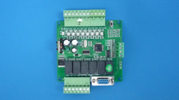
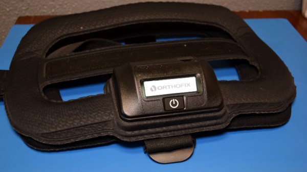
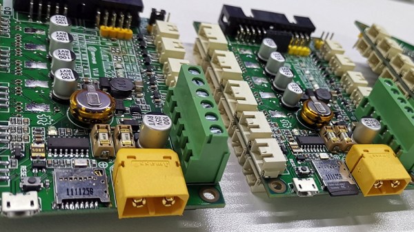
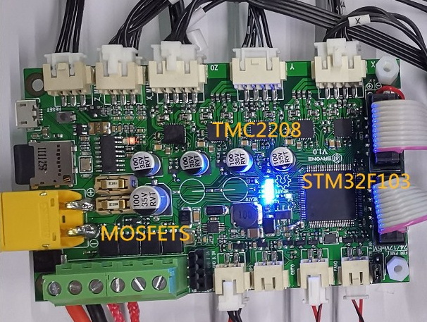
Self-balancing scooters a.k.a. Hoverboards are a great source of parts for such a project. Their high torque, direct drive brushless motors can drive loads of 100 kg or more. In addition, you also get a matching motor controller board, a rechargeable battery and its charging circuit. Most hoverboard controllers use the STM32F103, so flashing them with your own firmware becomes easy using a ST-link V2 programmer.

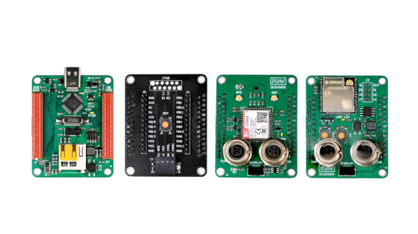
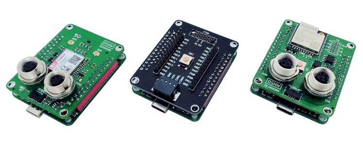
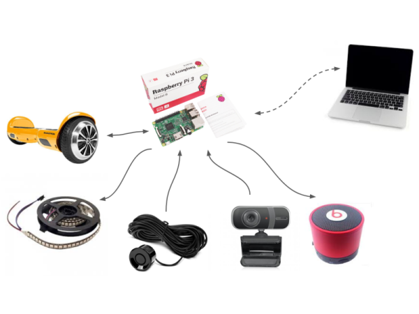
The next set of parts you need to build your robot is sensors. Some are cheap and easily available, such as microphones, contact switches or LDRs, while others such as ultrasonic distance sensors or LiDAR’s may cost a lot more. One source of cheap sensors are car parking assist transducers. An aftermarket parking sensor kit usually consists of four transducers, a control box, cables and display. Using a logic analyzer, [Isabelle] shows how you can poke around the output port of the control box to reverse engineer the data stream and decipher the sensor data. Once the data structure is decoded, you can then use some SPI bit-banging and voltage translation to interface it with the Raspberry Pi. Using the Pi makes it easy to add a cheap web camera, microphone and speakers to the Hoverbot.

Ikea is a hackers favourite, and offers a wide variety of hacker friendly devices and supplies. Their catalog offers a wide selection of fine, Swedish engineered products which can be used as enclosures for building robots. [Isabelle] zeroed in on a deep, circular plastic tray from a storage table set, stiffened with some plywood reinforcement. The tray offers ample space to mount the two motors, two castor wheels, battery and the rest of the electronics. Most of the original hardware from the hoverboard comes handy while putting it all together.

The software glue that holds all this together is JavaScript. The event-driven architecture of Node.js makes it a very suitable framework to use for Hoverbot. [Isabelle] has built a basic application allowing remote control of the robot. It includes a dashboard which shows live video and audio streams from the robot, buttons for movement control, an input box for converting text to speech, ultrasonic sensor visualization, LED lighting control, message log and status display for the motors. This makes the dashboard a useful debugging tool and a starting point for building more interesting applications. Check the build log for all the juicy details. Which other products from the Ikea catalog can be used to build the Hoverbot? How about a robotic Chair?

Continue reading “Turning That Old Hoverboard Into A Learning Platform”

Servos Do The Plucking In This MIDI Music Box

It started with a cheap, punch-card programmable manual music box. Thirty-one hobby servos later, it ended as an automated MIDI music box, with a short pit stop as a keyboard-driven MIDI device.

If you think you’ve seen the music box in [Mitxela]’s video below before, you’re right. [Martin], musician, inventor, and father of the marvelous marble music machine, took an interest in these music boxes and their programming a while back. Like [Martin], [Mitxela] started his music box project with punch card programming, but he quickly grew tired of the bothersome process, even after automating production with a laser cutter. He decided to do away with the punch cards completely and devised a method to pluck all 30 notes using a few large handfuls of hobby servos. One servo, converted to continuous rotation, spins the drum, with the rest linked to small laser-cut acrylic plectrums via stiff brass wire. The fingers imitate the punched holes passing over the drum and pluck the notes according to MIDI messages. The whole thing can draw quite a bit of current, so in addition to a beefy power supply, [Mitxela] optimized the code to minimize power requirements. This had the happy consequence of reducing the latency enough to allow the music box to be played from a MIDI keyboard in real time.

A lot of work went into this one, but [Mitxela] isn’t resting on his laurels; he has a full slate of improvements that he wants to tackle, not least of which is SD card support for MIDI files to turn this into a jukebox. We’re looking forward to the updates.

Continue reading “Servos Do The Plucking In This MIDI Music Box”

Better LEDs Through DMA

While regular Hackaday readers already know how to blink a LED with a microcontroller and have moved onto slightly more challenging projects such as solving the Navier-Stokes equations in 6502 assembly, that doesn’t mean there’s not space for newbies. [Rik] has published a great tutorial on abusing DMA for blinkier glowy things. Why would anyone want to learn about DMA techniques? For blinkier glowy things, of course.

This tutorial assumes knowledge of LED multiplexing and LED matrices, or basically a bunch of LEDs connected together on an XY grid. The naive way to drive an 8×8 grid of LEDs is attaching eight cathodes to GPIO pins on a microcontroller, attaching the eight anodes to another set of GPIO pins, and sourcing and sinking current as required. The pin count can be reduced with shift registers, and LED dimming can be implemented with PWM. This concludes our intensive eight-week Arduino course.

Thanks to microcontrollers that aren’t trapped in the 1980s, new techniques can be used to drive these LED matrices. Most of the more powerful ARM microcontrollers come with DMA, a peripheral for direct memory access. Instead of having the CPU do all the work, the DMA controller can simply shuffle around bits between memory and pins. This means blinker projects and glowier LEDs.

[Rik]’s method for DMAing LEDs includes setting up a big ‘ol array in the code, correctly initializing the DMA peripheral, and wiring up the LED matrix to a few of the pins. This technique can be expanded to animations with 64 levels of brightness, something that would take an incredible amount of processing power (for a microcontroller, at least) if it weren’t for the DMA controller.

The setup used in these experiments is an STM32F103 Nucleo board along with the OpenSTM32 IDE. [Rik] has released all the code over on GitHub, and you are, of course, encouraged to play around.