Adding Sensors To Improve Your Curling Game? Turns Out It’s Really Hard

Sometimes, a project turns out to be harder than expected at every turn and the plug gets pulled. That was the case with [Chris Fenton]’s efforts to gain insight into his curling game by adding sensors to monitor the movement of curling stones as well as the broom action. Luckily, [Chris] documented his efforts and provided us all with an opportunity to learn. After all, failure is (or should be) an excellent source of learning.

The first piece of hardware was intended to log curling stone motion and use it as a way to measure the performance of the sweepers. [Chris] wanted to stick a simple sensor brick made from a Teensy 3.0 and IMU to a stone and log all the motion-related data. The concept is straightforward, but in practice it wasn’t nearly as simple. The gyro, which measures angular velocity, did a good job of keeping track of the stone’s spin but the accelerometer was a different story. An accelerometer measures how much something is speeding up or slowing down, but it simply wasn’t able to properly sense the gentle and gradual changes in speed that the stone underwent as the ice ahead of it was swept or not swept. In theory a good idea, but in practice it ended up being the wrong tool for the job.

The other approach [Chris] attempted was to make a curling broom with a handle that lit up differently based on how hard one was sweeping. It wasn’t hard to put an LED strip on a broom and light it up based on a load sensor reading, but what ended up sinking this project was the need to do it in a way that didn’t interfere with the broom’s primary function and purpose. Even a mediocre curler applies extremely high forces to a broom when sweeping in a curling game, so not only do the electronics need to be extremely rugged, but the broom’s shaft needs to be able to withstand considerable force. The ideal shaft would be a clear and hollow plastic holding an LED strip with an attachment for the load sensor, but no plastic was up to the task. [Chris] made an aluminum-reinforced shaft, but even that only barely worked.

We’re glad [Chris] shared his findings, and he said the project deserves a more detailed report. We’re looking forward to that, because failure is a great teacher, and we’ve celebrated its learning potential time and again.

Turntable Spins Color And Sound Together

If you can’t grow your own synesthesia, buying electronics to do it for you is fine. Such is the case with the CHROMATIC by [Xavier Gazon], an artist who turns all kinds of electronics into circuit-bent musical art pieces. His project turns an old Philips Music 5120 turntable into a colorful MIDI sequencer, inspired by older 20th century instruments such as the Optophonic Piano and the Luminaphone.

The CHROMATIC uses colored pucks placed on a converted turntable to perform a looping sequence of chords in a given musical scale, generating MIDI data as output. Where its inspirations used primitive optics as their medium, this project employs a Teensy microcontroller and two modern optical sensors to do the work. One of these is a simple infrared sensor which tracks a white spot on the edge of the turntable, generating a MIDI clock signal to keep everything quantized and in sync. The other is a color sensor mounted on the tone arm, which can tell what color it sees and the height of the arm from the turntable.

While the instrument is still in beta testing phase details on how notes are generated aren’t yet given, though the general idea is that they are dictated by the color the tone arm sees and its position above the platter. Moving the tone arm changes which pucks it tracks, and the speed of the turntable can also be adjusted, changing how the melody sounds.​

The CHROMATIC is a very interesting project, but it’s not the first optical-based turntable hack we’ve seen here. We’ve also seen a much weirder use for a color sensor, too. Check out the video of this one in action after the break.

Continue reading “Turntable Spins Color And Sound Together”

The Zen Of Mechanical Keyboard Wiring

Mechanical keyboards are all the rage right now, but the vast majority of them are purchased commercially. Only the most dedicated people are willing to put in the time and effort required to design and assemble their own custom board, and as you might imagine, we’ve featured a number of such projects here on Hackaday in the past.

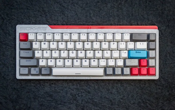
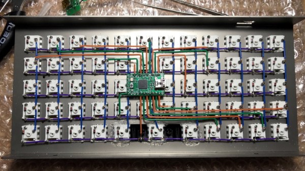
But what makes this particular mechanical keyboard build from [kentlamh] so special isn’t the final product (though it’s certainly quite nice), but the care he took when hand-wiring all of the switches to the Teensy 2.0 microcontroller that serves as its controller. There’s no PCB inside this custom board, it’s all rainbow colored wires, individual diodes, and the patience to put it all together with tweezers.

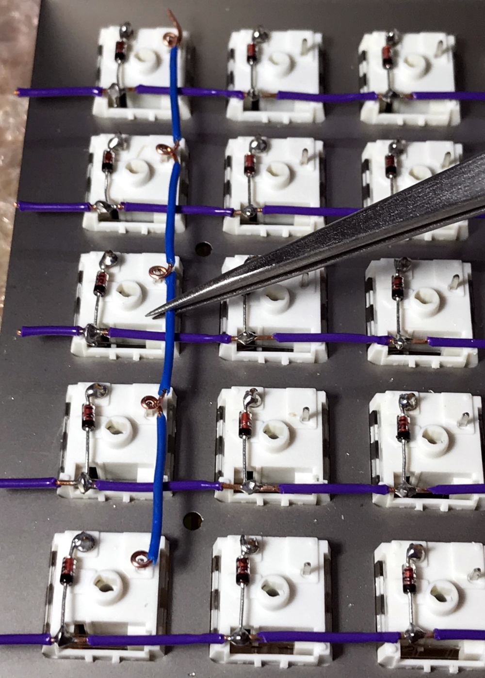
[kentlamh] takes the reader through every step of the wiring process, and drops a number of very helpful hints which are sure to be of interest to anyone who might be looking to embark on a similar journey. Such as bending the diode legs en masse on the edge of a table, or twisting them around a toothpick to create a neat loop that will fit over the pin on the back of the switch.

He also uses a soldering iron to melt away the insulation in the middle of the wires instead of suffering through hundreds of individual jumpers. We’ve seen this trick before with custom keyboards, and it’s one of those things we just can’t get enough of.

Some will no doubt argue that the correct way to do this would be to use an automatic wire stripper, and we don’t necessarily disagree. But there’s something undeniably appealing about the speed and convenience of just tapping the wire with the iron at each junction to give yourself a bit of bare copper to work with.

Even if you aren’t enough of a mechanical keyboard aficionado to travel all the way to Japan to attend the official meetup or discuss the finer points of their design at the Hackaday Superconference, there’s an undeniable beauty to this custom board. With a little guidance from [kentlamh], perhaps it will be your own handwired masterpiece that’s next to grace these pages.

[Thanks to Psybird for the tip.]

Millenium Falcon HID: Get Unity To Talk To Teensy

Here’s one that proves a hardware project can go beyond blinking LEDs and dumping massive chunks of data onto a serial console. Those practices are fine for some, but [dimtass] has found a more elegant hack for a more civilized age. His 3D Millennium Falcon model gets orientation data from his IMU as an an HID device.

The hardware involved is an MPU6050 6-axis sensor that is interfaced with a Teensy 3.2 board. [dimtass] documents his approach to calibrating the IMU going a bit further by using a Python script to generate offsets. We’ve advocated using Jupyter notebooks in the past and this is a good example of Jupyter plotting the data and visualizing the effect of the offsets in a second pass.

When in action, the Teensy reads IMU data and sends it over a USB RAW HID interface. For the uninitiated, HID transfers are more reliable than USB CDC transfers (virtual serial port) because they use smaller data chunks per event/transaction and usually don’t require special driversOn the computer side, [dimtass] has written a small application that gets the IMU values over the RAW HID and then provides it to the visualization application.

A 3D Millennium Falcon model is rendered in Unity, the popular open source game development engine. Even though Unity has an API, this particular approach is more OS specific using a shared-memory technique. The HID application writes to a file (/tmp/hid-shared-buffer) which is then read by Unity to make orientation changes to the rendered model.

[dimtass] provides lots of details on the tools used to bring his project to life and it can be a great starting point for more projects that need interfacing sensors with a visualization system. We have seen ways to turn a person’s head into a joystick and if you need a deeper dive into Unity, look no further.

Continue reading “Millenium Falcon HID: Get Unity To Talk To Teensy”

Flashing LEDs With MIDI, Note By Note

Musical keyboards that light up the correct notes to play have long been touted as a quick and easy way to learn how to play. They’re also fun to look at. [Shootingmaker] has developed a similar concept, with a keyboard lookalike, covered in LEDs (Youtube video, embedded below).

The project consists of a PCB, in which the design of the mask imitates the white and black notes of a piano. This makes it look like a keyboard, but as far as we can tell, it doesn’t actually work as one. All the notes are fitted with APA102 addressable LEDs, under the control of a Teensy 3.2 board, operating in USB-MIDI mode. The Teensy receives MIDI data, and then directs the individual LEDs to flash in different colors based on which MIDI channel fired the note.

It’s a fun way to visualise MIDI data, and we think it would be even more fun combined with a basic synthesis engine to make some noise. We suspect it wouldn’t be too hard to integrate the project into an existing instrument, either. Software is available on Github for those interested in replicating the project. You can use MIDI to control neon lights, too.
Continue reading “Flashing LEDs With MIDI, Note By Note”

LED Music Visualizer Bespeckles Your Bedroom

When it comes to wall-mounted ornamentation, get ready to throw out your throw-rugs and swap them for something that will pop so vividly, you’ll want to get your eyes checked. To get our eyes warmed up and popping, [James Best] has concocted a gargantuan 900-RGB-LED music visualizer to ensure that our bedrooms are bright and blinky on demand.

Like any other graduate from that small liberal-arts school in southern California, [James] started prototyping with some good old-fashioned blue tape. Once he had had his grid-spacing established, he set to work on 2-meter-by-0.5-meter wall mounted display from some plywood and lumber. Following some minor adhesive mishaps, James had his grid tacked down with Gaffers tape, and ready for visuals.

Under the hood, a Teensy is leveraging its DMA capabilities to conduct out a bitstream to 900 LEDs. By using the DMA feature and opting for a Teensy over the go-to Arduino, [James] is  using the spare CPU cycles to cook out some Fourier-Transformed music samples and display their frequency content.

We’ve covered folks proving the concept of driving oodles of WS2812B LEDs over DMA; it’s great seeing these ideas mature into a fully-featured project that lands on the walll. For more on chatting with WS2812B LEDs over DMA, have a look back into our archive.

Continue reading “LED Music Visualizer Bespeckles Your Bedroom”

This Two-Wheeled RC Car Is Rather Quick

Radio control cars have always been fun, it’s true. With that said, it’s hard to deny that true speed was unlocked when lithium polymer batteries and brushless motors came to the fore. [Gear Down For What?] built himself a speedy RC car of his own design, and it’s only got two wheels to boot (Youtube link, embedded below).

The design is of the self-balancing type – if you’re thinking of an angry unmanned Segway with a point to prove, you’re in the ballpark. The brains of the machine come thanks to a Teensy 3.6, which runs the PID loops for balancing and control. An MPU6050 gyroscope & accelerometer provide the necessary sensing to enable the ‘bot to keep itself upright in varied conditions. Performance is impressive, with the car reaching speeds in excess of 40 MPH and managing to handle simple ramps and bumps with ease. It’s all wrapped up in a 3D printed frame which held up surprisingly well to many crashes into tripods and tarmac.

Such builds are not just fun; they’re an excellent way to learn useful control skills that can serve you well in industry and your own projects. You can pick up the finer details of control systems in a university engineering course, or you could give our primer a whirl. When you’ve whipped up your first awesome project, we’d love to hear about it. Video after the break.

Continue reading “This Two-Wheeled RC Car Is Rather Quick”