There’s a problem with fuses. On the face of it, testing would seem to be a one-shot deal — exceed the rated current and see if it blows. But once you know the answer, the device is useless. If only there were a way to test fuses without damaging them.
As it turns out there is, and [Kerry Wong] weaves quite a tale about his attempts to non-destructively test fuses. The fuses in question are nothing fancy — just the standard glass tube type, from a cheap assortment kit off Amazon. Therein lies the problem: can such cheap devices be trusted? Finding out requires diving much deeper into the technology of fuses than many people will have done, including understanding how the thermal and electrical characteristics of the fuse element behave.
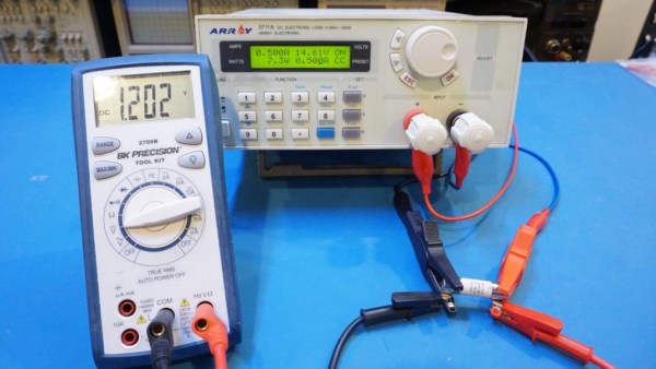
[Kerry]’s test setup is simple, consisting of a constant current power supply and a voltmeter across the fuse to measure the voltage drop caused by the resistance of the fuse element. As he ramps up the current, the voltage drop increases linearly due to the increase in resistance of the alloy with increasing temperature. That only lasts up to a point, where the fuse resistance starts increasing exponentially. Pushing much past the point where the resistance has doubled would blow the fuse, so that’s the endpoint of his tests. Perhaps unsurprisingly, his no-name fuses all went significantly beyond their rated current, proving that you get what you pay for. See the video below for the tests and an analysis of the results.
It’s handy to know there’s a way to check fuses without popping them, and we’ll file this one away for future reference. Don’t forget that you should always check the fuse when troubleshooting, because you never know what the last person did to it.
Continue reading “Test Unknown Fuses Without Destroying Them”