Are you a student? Are you part of a hackerspace? We have a contest going on right now where you can win a fancy new Prusa i3 MK3. The Repairs You Can Print contest is a challenge to do something useful with that machine that spits out tugboats. We’re looking for functional repairs of items around your house, office, or garage. Did you repair something with a 3D printer? Then you too can get in on the action! Enter now! Check out the entries!
You may know Flite Test as the group who do everything surrounding remote control flight (mostly fixed wings, a nice counter to the quadification of the hobby over the last few years). Flite Test designs and sells airplanes made out of Dollar Tree foam board, they have yearly, bi-coastal meetups, and they’re all-around awesome dudes. Now, they want to build the Disneyland of RC flight. [Josh Bixler], the face of Flite Test and a guy who has a plane named after him, wants to buy a golf course and turn it into the world’s best RC flying park, with a ~2000 foot grass strip for general aviation. We’re looking at their crowdfunding campaign, and it looks promising it might be funded by the time this goes live.
A while ago, [Peter Jansen], the guy who built a tricorder and a laser-cut CT scanner, made a magnetic camera. This Hall Effect camera is a camera for magnetism instead of light. Now, this camera has been fully built and vastly improved. He’s capturing ‘frames’ of magnetism in a spinning fan at 2000 Hz (or FPS, terminology kind of breaks down here), and it’s beautiful.
Oh thank God we can finally buy GPUs again. Try buying them with Bitcoin.
In the last few years, CITES, the Convention on International Trade in Endangered Species of Wild Fauna and Flora, has expanded. Originally, this was one of the treaties that banned the import or export of rhino horn, but recently this expanded to the export of rosewood thanks to increased demand in China for rosewood furniture. The laws of unintended consequences kicked into effect, and importing anything made out of rosewood is now a mess of permits and inspections at the border, including musical instruments. Travelling orchestras, for example, are at risk of having their string section confiscated because of rosewood tuning pegs. Cooler minds may now be prevailing, and there’s some hope the regulations may be changed during the next meeting of the CITES convention next year.
As noted a few months ago, there was a possibility of Broadcom buying Qualcomm for one… hundred… Billion dollars. This offer was rejected, with Qualcomm saying the offer wasn’t high enough. Broadcom fired back with an offer of $82 per share, or $121B. This offer was rejected this week.
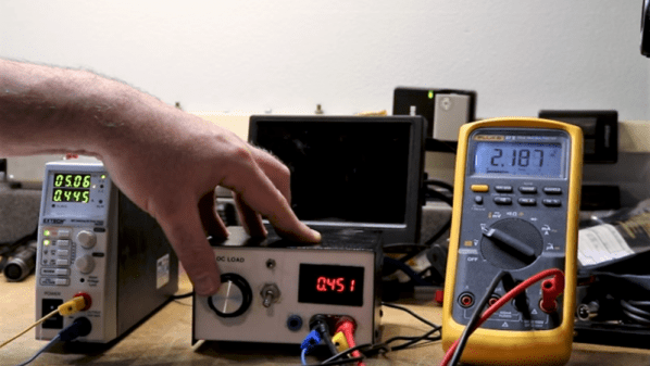
Need some EMC testing? [Zach]’s got your back. He’s reserved some time in a 10m EMC chamber for testing NeuroBytes this week. If you have an Open Source project that needs a pre-test scan for unintentional radiator, you can get in on the action. This is just a pre-test, you’re not getting certification, and you’re not going to test anything with radios, and you need to ship [Zach] your stuff. But still, free test time. Woo.