We all know, at least intellectually, that our computers are all built with lots of tiny transistors. But beyond that it’s a little hard to describe. They’re printed on a silicon wafer somehow, and since any sufficiently advanced technology is indistinguishable from magic, they miraculously create a large part of modern society. Even most computers from 40 or 50 years ago were built around various inscrutable integrated circuits. On the other hand, this computer goes all the way back to first principles and implements a complete processor out of individual transistors instead.
The transistor computer uses over 2000 individual transistors to implement everything comprising the 11-bit CPU. The creator, Reddit user [ Weekly_Salamander_78] also has an online interactive book that walks through each of the steps that is required to get to the point of having a working computer like this. Starting with a guide on building logic gates from transistors it will eventually cover the arithmetic logic unit, adders, memory, clocks, and everything else that is needed for the complete CPU to get up and running. The design does rely on an Arduino for memory to simplify some things, and in the end it’s able to run a Hello, World! program and play a simple dinosaur game as well.
Building a computer out of discrete components like this is an impressive accomplishment, although we might not envy the creator of it when it comes time for troubleshooting or maintenance of all of those individual components. Presumably it would be much easier to work on than something like a relay computer, but for now we’ll all take a moment to be thankful that almost no one needs to work on debugging vacuum tube computers anymore.


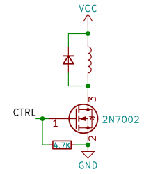 Perhaps, that’s the single most popular use for an NPN transistor – driving coils, like relays or solenoids. We are quite used to driving relays with BJTs, typically an NPN – but it doesn’t have to be a BJT, FETs often will do the job just as fine! Here’s an N-FET, used in the exact same configuration as a typical BJT is, except instead of a base current limiting resistor, we have a gate-source resistor – you can’t quite solder the BJT out and solder the FET in after you have designed the board, but it’s a pretty seamless replacement otherwise. The freewheel (back EMF protection) diode is still needed for when you switch the relay and the coil produces wacky voltages in protest, but hey, can’t have every single aspect be superior.
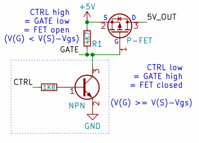 Here’s a simple FET circuit that lets you switch power to, say, a USB port, kind of like a valve that interrupts the current flow. This circuit uses a P-FET – to turn the power on, open the FET by bringing the GATE signal down to ground level, and to switch it off, close the FET by bringing the GATE back up, where the resistor holds it by default. If you want to control it from a 3.3 V MCU that can’t handle the high-side voltage on its pins, you can add a NPN transistor section as shown – this inverts the logic, making it into a more intuitive “high=on, low=off”, and, you no longer risk a GPIO!