Maybe you do it out of respect for the dogs and parents of young children in the neighborhood. Or maybe you do it because they’re harmful to the environment, or just because it’s too darn cold outside. Whatever your reasoning for not setting off fireworks, don’t fret — you can probably put together your own silent one-dimensional “fireworks” display from what you’ve got in the parts bin.
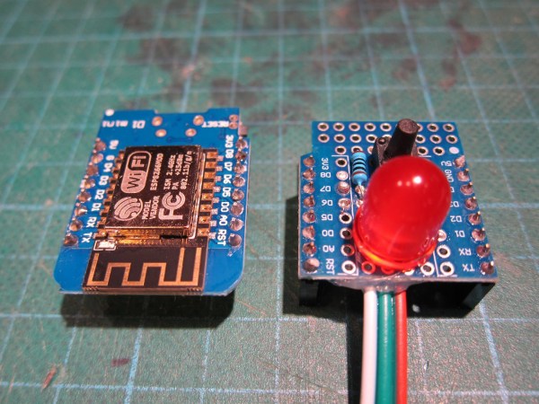
 [Daniel Westhof]’s design is simple, requiring little more than a Wemos D1 Mini and a strip of WS2812 LEDs. Once activated, a red rocket shoots up from the ground and detonates, sending lights in both directions on the strip to imitate the bombs bursting in air. It’s controlled with a small push button switch, and there’s a deliciously large red LED indicator that shows the thing is ready for detonation.
You might be surprised to find that there’s a wide array of 1D gaming and animation projects out there, many of which made possible by the ubiquitous addressable RGB LED strip. We’ve seen a dungeon crawler, at least two different versions of the classic PONG, and even the makings of a simplified Wolfenstein.