Build a $35 400 MHz Logic Analyzer

Build A 400 MHz Logic Analyzer For $35

What do you do when you’re a starving student and you need a 400 MHz logic analyzer for your digital circuit investigations? As [nanofix] shows in a recent video, you find one that’s available as an open hardware project and build it yourself.

The project, aptly named LogicAnalyzer was developed by [Dr. Gusman] a few years back, and has actually graced these pages in the past. In the video below, [nanofix] concentrates on the mechanics of actually putting the board together with a focus on soldering. The back of the build is the Raspberry Pi Pico 2 and the TXU0104 level shifters.

If you’d like to follow along at home, all the build instructions and design files are  available on GitHub. For your convenience the Gerber files have been shared at PCBWay

Of course we have heaps of material here at Hackaday covering logic analyzers. If you’re interested in budget options check out $13 Scope And Logic Analyzer Hits 18 Msps or how to build one using a ZX Spectrum! If you’re just getting started with logic analyzers (or if you’re not sure why you should) check out Logic Analyzers: Tapping Into Raspberry Pi Secrets.

Continue reading “Build A 400 MHz Logic Analyzer For $35”

The Saleae logic analyzer software is shown. One PWM channel is active, with values of 0x0001 displayed above the individual waveforms. On the right panel of the app, a trigger mode configuration panel is open for the simple parallel analyzer.

Simple Triggering For Saleae Logic Analyzers

Saleae logic analyzers seem to have it all: good sampling rates, convenient protocol decoding, and plenty of channels – but not a good way to set rising or falling-edge triggering. [James] found this rather inconvenient when debugging embedded devices, and shared a workaround that replicates these simple triggering modes.

Crucially, the logic analyzer’s software has a repeated triggering mode that fires when the protocol decoder detects a preset value. [James] used a clever trick to turn this into a rising-edge trigger: he set up a simple parallel analyzer, and set the signal in question as both the sampled channel and the clock signal. Since he wanted to detect the rising edge, he set the clock mode accordingly. Next, he loaded the simple parallel decoder’s trigger configuration and set it to detect a value of one, the value of a high signal. When he ran the simple parallel trigger, every rising edge of the input signal would trigger the clock to check for a high value on the line, in turn triggering the analyzer.

It’s also possible to set up a falling-edge trigger by selecting the falling-edge clock mode and setting the trigger mode to detect a value of zero. Setting up more complex triggers involving multiple channels is as simple as calculating the hexadecimal value of the desired state and setting the parallel decoder to trigger on that value. For example, if you want to trigger when one input is low and another is high, you can set the decoder to trigger on a value or one or two, depending on which order the inputs come in.

If all this makes you interested in Saleae logic analyzers, we’ve seen them used for everything from floppy disk preservation to signal generation. We’ve even reviewed their earliest model back in 2009.

Continue reading “Simple Triggering For Saleae Logic Analyzers”

The ZX Spectrum Logic Analyzer

We know [Happy Little Diodes] frequently works with logic analyzer projects. His recent wireless logic analyzer for the ZX Spectrum is one of the oddest ones we’ve seen in a while. The heart of the system is an RP2040, and there are two boards. One board interfaces with the computer, and another hosts the controller.

The logic analyzer core is powered by a common open-source analyzer from [Eldrgusman]. This is one of the nice things about open source tools. Most people probably don’t need a logic analyzer that plugs directly into a ZX Spectrum. But if you do, it is fairly simple to repurpose a more generic piece of code and rework the hardware, if necessary.

Continue reading “The ZX Spectrum Logic Analyzer”

Pico Logic Analyzer Gets New Version

[Happy Little Diodes] built a Pi Pico logic analyzer designed by [El Dr. Gusman] using the original design. But he recently had a chance to test the newest version of the design, which is a big upgrade. You can see his take on the new design in the video below.

The original design could sample 24 channels at 100 MHz and required two different PCBs. The new version uses a single board and can operate up to 400 MHz. There’s also a provision for chaining multiple boards together to get more channels. You can set the level shifters to use 5 V, 3.3 V, or an external voltage. Since [Happy] is working on a ZX Spectrum, the 5 V conversion is a necessity.

The code is on GitHub, although it warns you that version six — the one seen in the video — isn’t stable, so you might have to wait to make one on your own. The software looks impressive and there may be some effort to integrate with Sigrok.

If you missed our coverage of the earlier version, you can still catch up. Dead set on Sigrok support? [Pico-Coder] can help you out.

Continue reading “Pico Logic Analyzer Gets New Version”

Logic Analyzers: Decoding And Monitoring

Last time, we looked into using a logic analyzer to decode SPI signals of LCD displays, which can help us reuse LCD screens from proprietary systems, or port LCD driver code from one platform to another! If you are to do that, however, you might find a bottleneck – typically, you need to capture a whole bunch of data and then go through it, comparing bytes one by one, which is quite slow. If you have tinkered with Pulseview, you probably have already found an option to export decoded data – all you need to do is right-click on the decoder output and you’ll be presented with a bunch of options to export it. Here’s what you will find:

2521888-2521888 I²C: Address/data: Start
2521896-2521947 I²C: Address/data: Address write: 22
2521947-2521954 I²C: Address/data: Write
2521955-2521962 I²C: Address/data: ACK
2521962-2522020 I²C: Address/data: Data write: 01
2522021-2522028 I²C: Address/data: ACK
2522030-2522030 I²C: Address/data: Start repeat
2522038-2522089 I²C: Address/data: Address read: 22
2522089-2522096 I²C: Address/data: Read
2522096-2522103 I²C: Address/data: ACK
2522104-2522162 I²C: Address/data: Data read: 91
2522162-2522169 I²C: Address/data: NACK
2522172-2522172 I²C: Address/data: Stop

Whether on the screen or in an exported file, the decoder output is not terribly readable – depending on the kind of interface you’re sniffing, be it I2C, UART or SPI, you will get five to ten lines of decoder output for every byte transferred. If you’re getting large amounts of data from your logic analyzer and you want to actually understand what’s happening, this quickly will become a problem – not to mention that scrolling through the Pulseview window is not a comfortable experience.

The above output could look like this: 0x22: read 0x01 ( DEV_ID) = 0x91 (0b10010001). Yet, it doesn’t, and I want to show you how to correct this injustice. Today, we supercharge Pulseview with a few external scripts, and I’ll show you how to transfer large amounts of Sigrok decoder output data into beautiful human-readable transaction printouts. While we’re at it, let’s also check out commandline sigrok, avoiding the Pulseview UI altogether – with sigrok-cli, you can easily create a lightweight program that runs in the background and saves all captured data into a text file, or shows it on a screen in realtime! Continue reading “Logic Analyzers: Decoding And Monitoring”

Modern Microcontroller Boosts Classic Logic Analyzer To New Heights

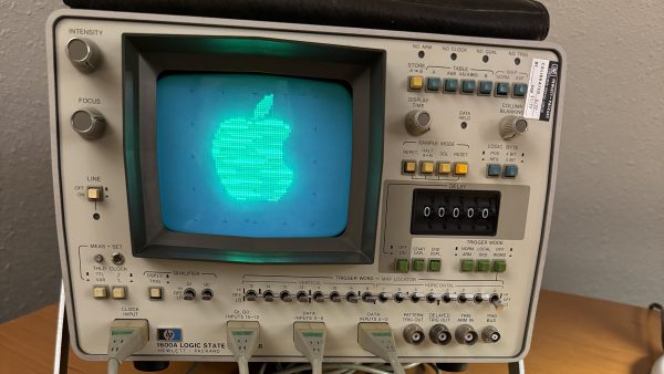
[Ted Fried] recently found a beautiful HP 1600A/1607A logic analyzer set. State of the art in 1975, it looks like glorious Space Age equipment today. He decided to hook it up some modern gear to put it through its paces.

Wanting to give the equipment a proper shakedown, he enlisted a Teensy 4.1 to spit a deluge of logic at the HP unit. The microcontroller was tasked with generating 32 data signals along with two clock outputs to give the analyzer plenty to analyze. The HP 1600A handled this no problem, so [Ted] kept tinkering.

His next feat was to explore the addressable “MAP” function of the unit, which allowed writing to the 64×64 pixel display. The Teensy 4.1 was easily able to send images to the display, but [Ted] isn’t stopping there. He’s got plans to do the usual thing and get Bad Apple going on the hardware.

Getting a logic analyzer to analyze logic isn’t much of a hack, sure. But it’s instructive of how to approach working with such hardware. If you want to spit a bunch of logic out fast, a Teensy 4.1 is a great choice because it’s got a ton of IO and a ton of clock cycles to tickle it with.

We enjoyed seeing this old piece of hardware light up the phosphors once more. If you’ve got your own projects going on with classic bits of HP test gear, don’t hesitate to let us know!

Modern Control Of A Logic Analyzer

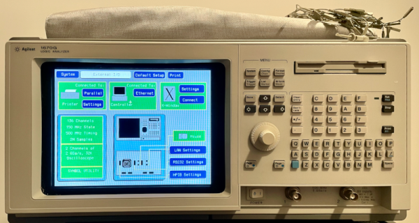
When you think of a logic analyzer today, you might think of a little USB probe that can measure a few signals and decoding for various serial buses. But actual logic analyzers were high-speed multichannel hardware with sophisticated ways to clock and trigger. [Tom] picked up an HP1670G on the surplus market and was impressed that it could sample 136 channels at 500 MHz. The circa-2000 machine has a front panel, but if you really wanted to use it, you wanted to use an X terminal. [Tom] shows us how that works with modern Linux software.

Continue reading “Modern Control Of A Logic Analyzer”