$13 Scope And Logic Analyzer Hits 18 Msps

We aren’t sure what’s coolest about [Richard Testardi’s] Flea-Scope. It costs about $13 plus the cost of making the PCB. It operates at 18 million samples per second. It also doesn’t need any software — you connect to it with your browser! It works as an oscilloscope, a logic analyzer, and a waveform generator. Not bad. The board is basically a little life support around a PIC32MK and the software required to run it.

Of course, for $13, you need to temper your expectations. One analog input reads from -6 to 6V (hint: use a 10X probe). The goal was for the instrument to be accurate within 2%.  There are also nine digital inputs sampled simultaneously with the analog sampling. The signal generator portion can output a 4 MHz square wave or a 40 kHz arbitrary waveform.

Continue reading “$13 Scope And Logic Analyzer Hits 18 Msps”

Logic Analyzers: Capabilities And Limitations

Last time, we’ve used a logic analyzer to investigate the ID_SD and ID_SC pins on a Raspberry Pi, which turned out to be regular I2C, and then we hacked hotplug into the Raspberry Pi camera code with an external MCU. Such an exercise makes logic analyzers look easy, and that’s because they are! If you have a logic analyzer, you’ll find that a whole bunch of hacks become available to you.

In this article, let’s figure out places where you can use a logic analyzer, and places where you can’t. We’ll start with the first limitation of logic analyzers – capture speed. For instance, here’s a cool thing you can buy on Aliexpress – a wristband from TTGO that looks like a usual fitness tracker, but has an ESP32 in it, together with an IMU, an RTC, and an IPS screen! The seller also has an FFC-connectable devboard for programming this wristband over UART, plus vibromotor and heartrate sensor expansion modules.

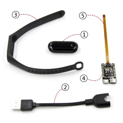
You can run C, MicroPython, Rust, JavaScript, or whatever else – just remember to bring your own power saving, because the battery is super small. I intended to run MicroPython on it, however, and have stumbled upon a problem – the ST7735-controller display just wouldn’t work with the st7735.py library I found; my image would be misaligned and inverted.

The specifications didn’t provide much other than “ST7735, 80×160”. Recap – the original code uses an Arduino (C++) ST7735 library and works well, and we have a MicroPython ST7735 library that doesn’t. In addition to that, I was having trouble getting a generic Arduino ST7735 library to work, too. Usually, such a problem is caused by the initialization commands being slightly different, and the reason for that is simple – ST7735 is just the name of the controller IC used on the LCD panel.

Each display in existence has specifics that go beyond the controller – the pixels of the panel could be wired up to the controller in a bunch of different ways, with varying offsets and connection types, and the panel might need different LCD charge pump requirements – say, depending on the panel’s properties, you might need to write 0x10 into a certain register of the ST7735, or you will need 0x40. Get one or more of these registers wrong, and you’ll end up with a misaligned image on your display at best, or no output at worst. Continue reading “Logic Analyzers: Capabilities And Limitations”

Logic Analyzers: Tapping Into Raspberry Pi Secrets

Today, I’d like to highlight a tool that brings your hacking skills to a whole new level, and does that without breaking the bank – in fact, given just how much debugging time you can save, how many fun pursuits you can unlock, and the numerous features you can add, this might be one of the cheapest tools you will get. Whether it’s debugging weird problems, optimizing your code, probing around a gadget you’re reverse-engineering, or maybe trying to understand someone’s open-source library, you are likely missing out a lot if you don’t have a logic analyzer on hand!

It’s heartbreaking to me that some hackers still don’t know the value that a logic analyzer brings. Over and over again, tactical application of a logic analyzer has helped me see an entirely different perspective on something I was hacking on, and that’s just the thing I’d like to demonstrate today.

Diving In

A logic analyzer has a number of digital inputs, and it continuously reads the state of these digital inputs, sending them to your computer or showing them on a screen – it’s like a logic-level-only oscilloscope. If you have an I2C bus with one MCU controlling a sensor, connect a logic analyzer to the clock and data pins, wire up the ground, launch the logic analyzer software on your computer, and see what’s actually happening.

For instance, have you ever noticed the ID_SC and ID_SD pins on the Raspberry Pi GPIO connector? Are you wondering what they’re for? Don’t you want to check what actually happens on these pins? Let’s do that right now! Continue reading “Logic Analyzers: Tapping Into Raspberry Pi Secrets”

ChatGPT Powers A Different Kind Of Logic Analyzer

If you’re hoping that this AI-powered logic analyzer will help you quickly debug that wonky digital circuit on your bench with the magic of AI, we’re sorry to disappoint you. But if you’re in luck if you’re in the market for something to help you detect logical fallacies someone spouts in conversation. With the magic of AI, of course.

First, a quick review: logic fallacies are errors in reasoning that lead to the wrong conclusions from a set of observations. Enumerating the kinds of fallacies has become a bit of a cottage industry in this age of fake news and misinformation, to the extent that many of the common fallacies have catchy names like “Texas Sharpshooter” or “No True Scotsman”. Each fallacy has its own set of characteristics, and while it can be easy to pick some of them out, analyzing speech and finding them all is a tough job.

Continue reading “ChatGPT Powers A Different Kind Of Logic Analyzer”

A CRT Monitor From An Obsolete Logic Analyzer

The designers of older equipment that contained a CRT monitor rarely made the effort to design their own driver and deflection circuitry. Instead they were more likely to buy an off  the shelf assembly from a monitor manufacturer, and simply supply it with their video. [TomV] has an old HP 16500A logic analyzer, and in it he found a Sony monitor chassis. With a quest for a microfiche service manual and a bit of reverse engineering, he was able to hook it up to a VGA port and use it as an extension monitor for his laptop.

The monitor chassis is a Sony CHM-9001-00, which sports their 10″ Trinitron tube. These were among the very best CRT tubes of the day, making it the type of module 1990s hacker would have been very pleased to get their hands on. Here in 2022 a look at the monitor’s 40-pin connector reveals a standard RGB interface which the service manual confirms is within the voltage range to be driven from a VGA output. A Thinkpad X220 is pressed into service, with a 576 by 360 pixel at 60 Hz video mode defined, and there we have it, a modern desktop on an obsolete piece of test equipment.

The intended destination for this monitor is a small arcade cabinet, so it needed to be independent of the HP chassis. The required 120 VDC supply comes from an inverter designed for solar battery charging, which balked at the inrush current from the monitor when fed with 12 V. Increasing the supply voltage on the low voltage side solved that, leading to a very serviceable monitor. We have no use for one, but we’d be lying if we said we didn’t want one.

Perhaps you may have wondered, what made Trinitrons so good?

Mis-captured signal transitions shown on the screen of the LA104, with problematic parts circled in red.

When Your Logic Analyzer Can’t Tell Good And Bad Signals Apart

[Avian] has picked up a Miniware LA104 – a small battery-powered logic analyzer with builtin protocol decoders. Such analyzers are handy tools for when you quickly need to see what really is happening with a certain signal, and they’re cheap enough to be sacrificial when it comes to risky repairs. Sadly, he stumbled upon a peculiar problem – the analyzer would show the signal glitching every now and then, even at very low bitrates. Even more surprisingly, the glitches didn’t occur in the signal traces when exported and viewed on a laptop.

A Pulseview window showing that the problem is not present in the exported capturesHe dug into the problem, as [Avian] does. Going through the problem-ridden capture files helped him realize that the glitch would always happen when one of the signal edges would be delayed by a few microseconds relative to other signal edges — a regular occurrence when it comes to digital logic. This seems to stem from compression being used by the FPGA-powered “capture samples and send them” part of the analyzer. This bug only relates to the signal as it’s being displayed on the analyzer’s screen, and turned out that while most of this analyzer’s interface is drawn by the STM32 CPU, the trace drawing part specifically was done by the FPGA using a separate LCD interface.

It would appear Miniware didn’t do enough testing, and it’s impossible to distinguish a good signal from a faulty one when using a LA104 – arguably, the primary function of a logic analyzer. In the best of Miniware traditions, going as far as being hostile to open-source firmware at times, the FPGA bistream source code is proprietary. Thus, this bug is not something we can easily fix ourselves, unless Miniware steps up and releases a gateware update. Until then, if you bought a LA104, you can’t rely on the signal it shows on the screen.

When it comes to Miniware problems, we’ve recently covered a Miniware tweezer repair, requiring a redesign of the shell originally held together with copious amount of glue. At times, it feels like there’s something in common between glue-filled unrepairable gadgets and faulty proprietary firmware. If this bug ruins the LA104 for you, hey, at least you can reflash it to work as an electronics interfacing multitool.

Pico Makes Capable Logic Analyzer

A common enough microcontroller project is to create some form of logic analyzer. In theory, it should be pretty easy: grab some digital inputs, store them, and display them. But, of course, the devil is in the details. First, you want to grab data fast, but you also need to examine the trigger in real time — hard to do in software. You may also need input conditioning circuitry unless you are satisfied with the microcontroller’s input characteristics. Finally, you need a way to dump the data for analysis. [Gusmanb] has tackled all of these problems with a simple analyzer built around the Raspberry Pi Pico.

On the front and back ends, there is an optional board that does fast level conversion. If you don’t mind measuring 3.3 V inputs, you can forego the board. On the output side, there is custom software for displaying the results. What’s really interesting, though, is what is in between.

The simple PCB is completely optional.

The Pico grabs 24 bits of data at 100 MHz and provides edge and pattern triggers. This is impressive because you need to look at the data as you store it and that eats up a few instruction cycles if you try to do it in software, dropping your maximum clock rate. So how does this project manage it?

It uses the Pico’s PIO units are auxiliary dedicated processors that aren’t very powerful, but they are very fast and deterministic. Two PIO instructions are enough to handle the work for simple cases. However, there are two PIOs and each has four separate state machines. It still takes some work, but it is easier than trying to run a CPU at a few gigahertz to get the same effect. The fast trigger mode, in particular, abuses the PIO to get maximum speed and can even work up to 200 MHz with some limitations.

If you want to try it, you can use nothing more than a Pico and a jumper wire as long as you don’t need the level conversion. The project page mentions that custom software avoids using OpenBench software, which we get, but we might have gone for Sigrok drivers to prevent having to reinvent too many wheels. The author mentions that it was easier to roll your own code than conform to a driver protocol and we get that, too. Still, the software looks nice and even has an SPI protocol analyzer. It is all open source, so if you want other protocols before the author gets to them, you could always do it yourself.

If you do want a Pico and Sigrok, we’ve covered a project that does just that. Most of the logic analyzers we use these days we build into our FPGA designs.