Save Some Steps With This Arduino Rapid Design Board

We’re all familiar with the wide variety of Arduino development boards available these days, and we see project after project wired up on a Nano or an Uno. Not that there’s anything wrong with that, of course, but there comes a point where some hobbyists want to move beyond plugging wires into header sockets and build the microcontroller right into their project. That’s when one generally learns that development boards do a lot more than break the microcontroller lines out to headers, and that rolling your own design means including all that supporting circuitry.

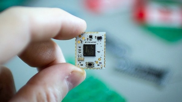
To make that transition easier, [Sean Hodgins] has come up with a simple Arduino-compatible module that can be soldered right to a PCB. Dubbed the “HCC Mod” for the plated half-circle castellations that allows for easy soldering, the module is based on the Atmel SAMD21 microcontroller. With 16 GPIO lines, six ADCs, an onboard 3.3 V regulator, and a reset button, the module has everything needed to get started — just design a PCB with the right pad layout, solder it on, and surround it with your circuitry. Programming is done in the familiar Arduino IDE so you can get up and running quickly. [Sean] has a Kickstarter going for the modules, but he’s also releasing it as open source so you’re free to solder up your own like he does in the video below.

It’s certainly not the first dev module that can be directly soldered to a PCB, but we like the design and can see how it would simplify designs. [Sean] as shown us a lot of builds before, like this army of neural net robots, so he’ll no doubt put these modules to good use.

Continue reading “Save Some Steps With This Arduino Rapid Design Board”

Double The Resolution, From An Arduino ADC

Analog-to-digital converters, or ADCs, are somewhat monolithic devices for most users, a black box that you ask nicely for the value on its input, and receive a number in return. For most readers, they will be built into whatever microcontroller is their platform of choice, and their resolution will be immutable, set by whatever circuitry is included upon the die. There are a few tricks that can be employed to get a bit more from a stock ADC though, and [Neris] has taken a look at a couple of them.

The first circuit doubles the resolution of an ADC, in this case, that of the Atmel chip in an Arduino, by converting its output from an integer to a signed integer. It performs this task with a precision rectifier, rectifying around a zero-crossing point half-way through the range of the analog value to be read and supplying a sign bit to the Arduino. The Arduino measures the rectified analog value to an integer, and applies the appropriate sign from the supplied bit value.

The second circuit takes a variation on the same technique but with two ADCs instead of one. A pair of PIC chips are used with their voltage references stacked one above the other, by taking both readings in combination a result with double the resolution can be derived.

You might ask why bother with these techniques. After all, there are plenty of higher-resolution ADCs on the market. But they’re useful techniques to know, should you ever need to extract the proverbial quart from a pint pot.

If ADCs are a mystery to you, you’re in luck. [Bil Herd] gave us a comprehensive introduction to the subject.

Portable DVD Player Gets Raspberry Pi Zero Upgrade

You might remember a time when people thought portable DVD players were a pretty neat idea. In the days before netbooks, cheap tablets, and arguably even the widespread adoption of smartphones, it seemed perfectly reasonable to lug around a device that did nothing but play movies. Today we look back at them as we would flip phones: a quaint precursor to the technology overload we find ourselves in currently. But the fact remains that millions of these comical little devices were pumped into the greedy maw of the consumer electronics market. They’re ripe for the hacking, all you need is some inspiration.

So if this grafting of a portable DVD player and the Raspberry Pi Zero W created by [nutsacrilege] doesn’t get you sniffing around your local second-hand store for a donor device, nothing will. By integrating a Pi running Kodi, the player gets a multi-media kick in the pants that arguably makes up for the rather archaic form factor. Not only can it play a wide array of local and online content, but it could even be used as portable game system if you were so inclined.

Rest assured, this isn’t some lazy five-minute mod. All of the original physical controls have been made functional by way of a MCP3008 ADC connected to the Pi’s GPIO and some clever Python scripting. Even the headphone jack was made functional by wiring it up to a USB sound card, and by integrating a tiny stripped down hub he was also able to add an external USB port. Who needs discs when you can plug in a flash drive full of content?

Speaking of which, [nutsacrilege] reports that the original functions of the device are still intact after all his modifications. So if you can get the museum to loan you one, you can even play a DVD on the thing as its creators intended.

With luck, this project will help spur on some more portable DVD player hacking, which we’ve seen precious little of so far. Frankly, it would be nice to see people cramming Raspberry Pi’s into something other than Game Boys for once.

[via /r/raspberry_pi]

A Compensated Thermocouple Amp, Ready For Arduino

When you want to measure temperature with an Arduino or other microcontrollers, there are a ton of options for sensors. Temperature chips and sensor modules abound, some with humidity sensors built-in and all with easy interfacing and an expansive supporting code library. But dip one of those sensors into, say, molten aluminum, and you’ve got a problem.

If you’re measuring something hot, you need a thermocouple. Trouble is, the signal from a thermocouple is pretty small, and needs amplification and compensation before being fed into the ADC of a typical microcontroller. Unable to find a commercial amp to meet his needs, [MonkHelios] built his own thermocouple amp for microcontrollers. The design is centered around an LTC2053 instrumentation amp, which does the job of converting the K-type thermocouple’s 40.6μV/°C output to a nicely scaled 10mV/°C range, just right for ADC consumption. He also thoughtfully included an LT1025 cold-junction compensator; thermocouple amps are referenced to 0°C, so the compensator measures the actual temperature of the cold end of the junction and scales the output accordingly. The whole amp is nicely laid out on a DIY single-sided PCB with meticulously applied solder mask — this is one of the nicest home-etched boards we’ve seen in a long time.

[Bil Herd] designed a similar thermocouple amp not too long ago himself, so you might check that out too.  Or maybe you need the basics of instrumentation amps? Our “Beyond Measure” series will get you started.

Basic Sequencer For Your Synth Rack

Sequencers are useful for bringing regular structure to your music, particularly if you enjoy noodling around with rackmount synthesizers. [little-scale] is here to share an ADC Binary Gate sequencer for your setup.

In a quest for ever greater minimalism, the build relies on a barebones ATMega328p without an external oscillator. Instead, the chip’s internal RC oscillator is used instead. It’s possible to still use this with the Arduino IDE, as [little-scale] shares here.

The music production begins with a clock input signal, which is patched in from elsewhere in the rack synth. The sequencing is controlled with potentiometers. There are four potentiometers, and four corresponding output channels.  The pots are all read with the onboard analog to digital converters, and the position transformed into an 8-bit value, from 0 to 255. Our best understanding is that the 8-bit number is then used as the sequence to follow. For example, if the potentiometer is set to 255, which is 11111111 in binary, the sequencer will trigger on every beat. If instead the potentiometer was turned to around 2/3rds of the maximum, and the ADC reads a value of 170, in binary this is 10101010 which would trigger on every second beat.

It’s an interesting way to sequence several channels with the bare minimum of input devices. While it may not be the most intuitive system, it really suits the knob-and-dial noodling so relished by rackmount fanatics. Be sure to check out the video below for [little-scale]’s rackmount sounds and impressively pretty videography.  Never before did breadboards look so good.

New to rack mount synths? Check this one out.


When Is A 10-bit A/D An 8-bit A/D?

Marketing guys love bigger numbers. Bigger is better, right? After all, Subway called it a “footlong” not an 11-incher. So when it comes to analog to digital (A/D) conversion, more bits are better, right? Well, that depends. It is easy to understand that an A/D will have a low and high measurement and the low will be zero counts and the high will result in the maximum count for the number of bits. That is, an 8-bit device will top out at 255, a 10-bit at 1023, and so on.

The question is: are those bits meaningful? The answer depends on a few factors. Like most components we deal with, our ideal model isn’t reality, but maybe it is close enough.

Continue reading “When Is A 10-bit A/D An 8-bit A/D?”

Hackaday Prize Entry: Dynamometer For Post Stroke Rehabilitation

For those who have suffered a stroke, recovery is a long and slow process that requires rehabilitation to start as early as possible. Quite often, secondary stroke attacks complicate matters. Spasticity — muscle contraction and paresis — muscular weakness, are two of the many common after-effects of stroke. Recovery involves doing repeated exercises to strengthen the muscles and bring back muscle memory. Benchmarking progress becomes difficult when caregivers are only able to use qualitative means such as squeezing tennis balls to monitor improvement. To help provide quantitative measurements in such cases, [Sergei V. Bogdanov] is building a Dynamometer for Post-Stroke Rehabilitation. It is an Open Source, 4-channel differential force gauge for measuring and logging the progress of the patient. The device measures, graphs, and logs the force exerted by the four fingers when they push down on the four force gauges.

The device consists of four strain gauges obtained from cheap kitchen scales. The analog outputs from these are fed to HX-711 24-bit ADC boards. An Arduino Nano processes the data and displays it on two banks of eight-digit LED modules. [Sergei] also experimented with a 20×4 character LCD in place of the LED display. In the standalone mode, the device can only indicate the measured forces on the LED (or LCD) display which is calibrated to display either numerical values or a logarithmic scale. When connected to a serial port and using the (Windows only) program, it is possible to not only view the same information but also save it at regular, set intervals. The data can also be viewed in graphical form.

The project page provides links to their Arduino code, Windows monitor program as well as build instructions. Check out the related assistive technology project that [Sergei] is working on — A Post Stroke Spasticity Rehab Helper.

Continue reading “Hackaday Prize Entry: Dynamometer For Post Stroke Rehabilitation”