We’ve all seen the little USB power meters that have become popular since nearly every portable device has adopted some variation of USB for charging. Placed between the power source and the device under test, they allow you to see voltage and current in real time. Perfect for determining how long you’ll be able to run a USB powered device on batteries, or finding out if a USB power supply has enough current to do the business.
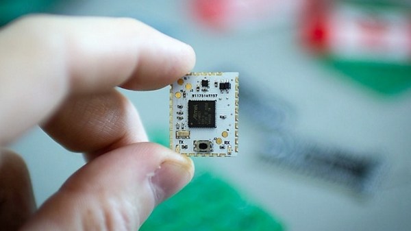
 [Jonas Persson] liked the idea of these cheap little gadgets, but wanted something a bit more scientific. His design, which he refers to as UPM, is essentially a “smart” version of those ubiquitous USB gadgets. Instead of just showing the data on a little LCD screen, it can now be viewed on the computer and analyzed. His little gadget even allows you to cut power to the device under test, potentially allowing for automated testing of things such as inrush current.
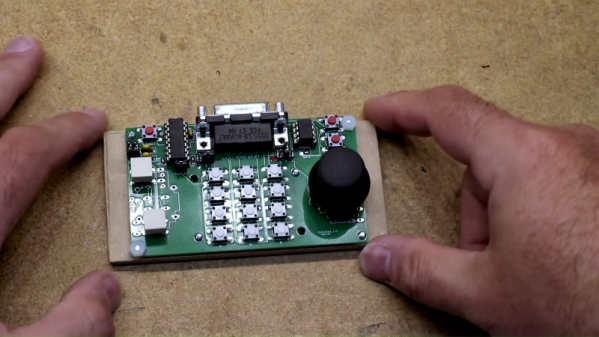
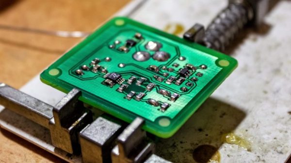
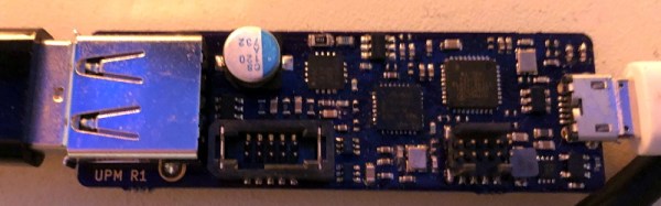
Essentially the UPM works in much the same way as the simple USB meters: one side of the device goes towards the upstream power source, and the device under test plugs into the other side. Between the two devices is a 16 bit ADC and differential amplifier which measures the voltage and current. There’s a header on the board which connects to the ADC if you wanted to connect the UPM to an external microcontroller or other data logging device.
But most likely you would be using the internal microcontroller to analyze the output of the ADC over I2C, which [Jonas] very cleverly connected to the upstream port with an integrated USB hub. One side of the hub goes off to the device being tested, and the other to the microcontroller. So the host device will see both the UPM’s integrated microcontroller and the target device at the same time. From there, you can use the ncurses user interface to monitor and control the device in real-time.
While the hardware looks more or less finished, [Jonas] has some more plans for the software side of UPM, including support for remote control and monitoring over TCP/IP as well as robust logging capabilities. This is definitely a very interesting project, and we’re excited to see it develop further.
In the past we’ve seen homebrew USB power meter builds, and even commercial offerings which boasted computer-based logging and analysis, so it was only a matter of time before somebody combined them into one.