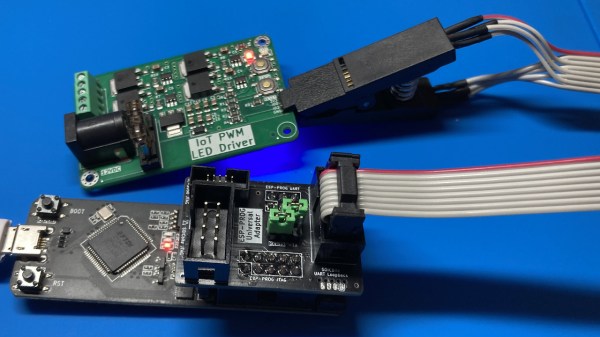
37C3: When Apple Ditches Lightning, Hack USB-C

[Thomas Roth], aka [Ghidraninja], and author of the [Stacksmashing] YouTube channel, investigated Apple’s Lightning port and created a cool debugging tool that allowed one to get JTAG on the device. Then, Apple went to USB-C for their new phones, and all his work went to waste. Oh well, start again — and take a look at USB-C.

Turns out, though, that the iPhone 15 uses the vendor-defined messages (VDM) capability of USB-PD to get all sorts of fun features out. Others had explored the VDM capabilities on Mac notebooks, and it turns out that the VDM messages on the phone are the same. Some more fiddling, and he got a serial port and JTAG up and running. But JTAG is locked down in the production devices, so that will have to wait for an iPhone 15 jailbreak. So he went poking around elsewhere.

He found some other funny signals that turned out to be System Power Management Interface (SPMI), one of the horribly closed and NDA-documented dialects owned by the MIPI Alliance. Digging around on the Interwebs, he found enough documentation to build an open-source SPMI plugin that he said should be out on his GitHub soon.

The end result? He reworked his old Lightning hardware tool for USB-C and poked around enough in the various available protocols to get a foothold on serial, JTAG, and SPMI. This is just the beginning, but if you’re interested in playing with the new iPhone, this talk is a great place to start. Want to know all about USB-C? We’ve got plenty of reading for you.

Using JTAG To Dump The Xbox’s Secret Boot ROM

When Microsoft released its first entry into the video game console market with the Xbox, a lot of the discussions at the time revolved around the fact that it used a nearly off-the-shelf Intel CPU and NVIDIA GPU solution. This made it quite different from the very custom consoles from Nintendo and Sony, and invited thoughts on running custom code on the x86 console. Although the security in the console was hacked before long, there were still some open questions, such as whether the secret boot ROM could have been dumped via the CPU’s JTAG interface. This is the question which [Markus Gaasedelen] sought to answer.

The reason why this secret code was originally dumped by intercepting it as it made its merry way from the South to the North Bridge (containing the GPU) of the Xbox was because Microsoft had foolishly left this path unencrypted, and because the JTAG interface on the CPU was left disabled via the TRST# pin which was tied to ground. This meant that without removing the CPU and adding some kind of interposer, the JTAG interface would not be active.

A small issue after the harrowing task of desoldering the CPU and reinstalling it with the custom interposer in place was to keep the system integrity check (enforced by an onboard PIC16 MCU) intact. With the CPU hooked up to the JTAG debugger this check failed, requiring an external injection of the signal on the I2C bus to keep the PIC16 from resetting the system. Yet even after all of this, and getting the secret bootrom code dumped via JTAG, there was one final system reset that was tied to the detection of an abnormal CPU start-up.

The original Xbox ended up being hacked pretty thoroughly, famously giving rise to projects like Xbox Media Center (XBMC), which today is known as Kodi. Microsoft learned their lesson though, as each of their new consoles has been more secure than the last. Barring some colossal screw-up in Redmond, the glory days of Xbox hacking are sadly well behind us.

Dumping script window, showing the bytes being dumped one by one from the STM chip

Need To Dump A Protected STM32F0x? Use Your Pico!

Sometimes, security mechanisms can be bypassed if you just do things slightly out of the ordinary. For instance, readout protection on microcontrollers is a given nowadays, to the point where it’s intentionally enabled and relied upon as a major technical measure to protect intellectual property. The gist is — when you connect to a microcontroller over its debug interface and then ask to read its flash memory, it will politely refuse. However, [Racerxdl] shows us that in practice, it’s not flawless protection – for certain chips, you just need to be a little quicker than usual.

Usually, flashing and debugging software will chat with the microcontroller for a bit, and probe parameters before going for any direct requests. However, if you skip the courtesy and bluntly get to the point immediately right after power is applied to the microcontroller, you can intimidate them just enough to give you one byte of its memory before it refuses to cooperate further. Since that can be any byte you wish, you can read the entire flash — one byte at a time.

You need to power cycle the chip before you can progress, so the hardware does involve a bit more than just an SWD interface, and it will take a fair bit more time than reading out a non-protected chip the usual way; plus, of course, the debugging interface needs to be active for this in the first place, which isn’t always the case. However, it still beats paying a few thousand dollars for a factory in China to decap your chip and read it out using a fancy machine.

[Racerxdl] didn’t just write a proof-of-concept for this attack – they implemented it for one of our favourite chips, the RP2040. As such, you no longer need an unobtainium STM32 to dump an unobtainium STM32.

To be clear, [Racerxdl] didn’t design this attack — it’s been around for some time now. Credit for that goes to Johanes Obermaier. All in all, this is a wonderful reminder that seemingly reliable security mechanisms can be foiled by the simplest tricks. For instance, if your chip erases the flash when you unlock its protection, you can just tell it not to.

Reverse Engineering Reveals EV Charger Has A Sense Of Security

As more and more electric vehicles penetrate the market, there’s going to have to be a proportional rise in the number of charging stations that are built into parking garages, apartment complexes, and even private homes. And the more that happens, the more chargers we’re going to start seeing where security is at best an afterthought in their design.

But as this EV charger teardown and reverse engineering shows, it doesn’t necessarily have to be that way. The charger is a Zaptec Pro station that can do up to 22 kW, and the analysis was done by [Harrison Sand] and [Andreas Claesson]. These are just the kinds of chargers that will likely be widely installed over the next decade, and there’s surprisingly little to them. [Harrison] and [Andreas] found a pair of PCBs, one for the power electronics and one for the control circuits. The latter supports a number of connectivity options, like 4G, WiFi, and Bluetooth, plus some RFID and powerline communications. There are two microcontrollers, a PIC and an ARM Cortex-A7.

Despite the ARM chip, the board seemed to lack an obvious JTAG port, and while some unpopulated pads did end up having a UART line, there was no shell access possible. An on-board micro SD card slot seemed an obvious target for attack, and some of the Linux images they tried yielded at least a partial boot-up, but without knowing the specific hardware configuration on the board, that’s just shooting in the dark. That’s when the NAND flash chip was popped off the board to dump the firmware, which allowed them to extract the devicetree and build a custom bootloader to finally own root.

The article has a lot of fascinating details on the exploit and what they discovered after getting in, like the fact that even if you had the factory-set Bluetooth PIN, you wouldn’t be able to get free charging. So overall, a pretty good security setup, even if they were able to get in by dumping the firmware. This all reminds us a little of the smart meter reverse engineering our friend [Hash] has been doing, in terms of both methodology and results.

Thanks to [Thinkerer] for the tip.

A Pi Pico connected to a MYIR Z-turn board with a set of jumper wires

Need A JTAG Adapter? Use Your Pico!

JTAG is a powerful interface for low-level debugging and introspection of all kinds of devices — CPUs, FPGAs, MCUs and a whole lot of complex purpose-built chips like RF front-ends. JTAG adapters can be quite obscure, or cost a pretty penny, which is why we’re glad to see that [Adam Taylor] from [ADIUVO] made a tutorial on using your Pi Pico board as a JTAG adapter. This relies on a project called XVC-Pico by [Dhiru Kholia], and doesn’t require anything other than a Pi Pico board itself — the XVC-Pico provides both a RP2040 firmware implementing the XVC (Xilinx Virtual Cable) specification and a daemon that connects to the Pico board and interfaces to tools like Vivado.

First part of the write-up is dedicated to compiling the Pico firmware using a Linux VM. There’s a pre-built .uf2 binary available in the GitHub repo, however, so you don’t have to do that. Then, he compiles and runs a daemon on the PC where the Pico is connected, connects to that daemon through Vivado, and shows successful single-stepping through code on a MYIR Z-turn board with a Xilinx XC7Z020. It’s worth remembering that, if your FPGA’s (or any other target’s) JTAG logic levels are 1.8V or 2.5V-based, you will need a level shifter between it and the Pi Pico, which is a board firmly in the 3.3V realm.

You just cannot beat the $3 price and the ease of setup. Pi Pico is shaping up to be more and more of a hardware multi-tool. Just a month ago, we covered how the Pico can work as a logic analyzer. A lot of that, we have the PIO peripherals to thank for — an assembly of state machines that even let you “bitbang” high-speed interfaces like DVI. If you’re interested in how PIO functions, there are some good write-ups around here. Lacking a Pi Pico, you can use this board’s bigger sister to interface with JTAG, too.

An “unbusy” USB-C Port Doubles-up For JTAG Programming

Board space is a premium on small circuit board designs, and [Alvaro] knows it. So instead of adding a separate programming port, he’s found a niche USB-C feature that lets him use the port that he’s already added both for its primary application and for programming the target microcontroller over JTAG. The result is that he no longer needs to worry about spending precious board space for a tiny programming port; the USB-C port timeshares for both!

In a Twitter thread (Unrolled Link), [Alvaro] walks us through his discovery and progress towards an encapsulated solution. It turns out that the USB-C spec supports a “Debug-Accessory Mode” specification, where some pins are allowed to be repurposed if pins CC1 and CC2 are pulled up to Logic-1. Under these circumstances, the pin functions are released, and a JTAG programmer can step in to borrow them. To expose the port to a programmer, [Alvaro] cooked up a small breakout board with a USB-C plug and separate microcontroller populated on it.

This board also handles a small quirk. Since [Alvaro’s] choice of programming pins aren’t reversible, the USB-C plug will only work one of the two ways it can be plugged in. To keep the user informed, this breakout board sports a red LED for incorrect orientation and a green LED for correct orientation–nifty. While this design quirk sacrifices reversibility, it preserves the USB 2.0 D+ and D- pins while also handling some edge cases with regard to the negotiating for access to the port.

Stick through [Alvaro]’s Twitter thread for progress pics and more details on his rationale behind his pin choices. Who knows? With more eyes on the USB-C feature, maybe we’ll see this sort of programming interface become the norm?

[Alvaro] is no stranger to Hackaday. In fact, take a tour back to our very first Supercon to see him chat about shooting lasers at moving targets to score points on a DEFCON challenge in the past

JTAG Hat Turns Raspberry Pi Into A Networked Debugger

Over the last year or so we’ve noticed a definite uptick in the number of folks using OpenOCD on the Raspberry Pi. It’s a cheap and convenient solution for poking around with various microcontrollers and embedded devices, but not always the most elegant. Looking to improve on the situation somewhat, [Matthew Mets] has been working on a purpose-built JTAG Hat to clean things up a bit.

Onboard level shifters allow you connect to JTAG and SWD interfaces from 1.8 to 5 V, and if you power the target device from the Pi itself, there’s even support for measuring the voltage and current. To connect up to your target, the open hardware board features a “legacy” pin header perfect for jumper wires, as well as a dedicated 10-pin Cortex Debug Connector. Whether you spin up your own or buy one assembled, it certainly looks like a tool worth having around if you often find yourself working with the appropriate chips.

In addition to the design files for the hardware, [Matthew] has also provided some nice documentation on how to get the software side of things up and running. Starting with a blank SD card, it walks you through the initial setup of the Raspberry Pi all the way through the installation and configuration of a patched version of OpenOCD designed to support the JTAG Hat.

If you spend more time working with 8-bit AVR chips, don’t worry. Last year we covered a similar project to turn everyone’s favorite Linux SBC into an all-in-one microcontroller development powerhouse.