Blame It On The Sockets: Forensic Analysis Of The Arecibo Collapse

Nearly three years after the rapid unplanned disassembly of the Arecibo radio telescope, we finally have a culprit in the collapse: bad sockets.

In case you somehow missed it, back in 2020 we started getting ominous reports that the cables supporting the 900-ton instrument platform above the 300-meter primary reflector of what was at the time the world’s largest radio telescope were slowly coming undone. From the first sign of problems in August, when the first broken cable smashed a hole in the reflector, to the failure of a second cable in November, it surely seemed like Arecibo’s days were numbered, and that it would fall victim to all the other bad luck we seemed to be rapidly accruing in that fateful year. The inevitable finally happened on December 1, when over-stressed cables on support tower four finally gave way, sending the platform on a graceful swing into the side of the natural depression that cradled the reflector, damaging the telescope beyond all hope of repair.

The long run-up to the telescope’s final act had a silver lining in that it provided engineers and scientists with a chance to carefully observe the failure in real-time. So there was no real mystery as to what happened, at least from a big-picture perspective. But one always wants to know the fine-scale details of such failures, a task which fell to forensic investigation firm Thornton Tomasetti. They enlisted the help of the Columbia University Strength of Materials lab, which sent pieces of the failed cable to the Oak Ridge National Laboratory’s High Flux Isotope reactor for neutron imaging, which is like an X-ray study but uses streams of neutrons that interact with the material’s nuclei rather than their electrons.

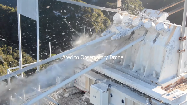
The full report (PDF) reveals five proximate causes for the collapse, chief of which is “[T]he manual and inconsistent splay of the wires during cable socketing,” which we take to mean that the individual strands of the cables were not spread out correctly before the molten zinc “spelter socket” was molded around them. The resulting shear stress caused the zinc to slowly flow around the cable strands, letting them slip out of the surrounding steel socket and — well, you can watch the rest below for yourself.

As is usually the case with such failures, there are multiple causes, all of which are covered in the 300+ page report. But being able to pin the bulk of the failure on a single, easily understood — and easily addressed — defect is comforting, in a way. It’s cold comfort to astronomers and Arecibo staff, perhaps, but at least it’s a lesson that might prevent future failures of cable-supported structures.

Continue reading “Blame It On The Sockets: Forensic Analysis Of The Arecibo Collapse”

Swapped ROM Revives Ailing HP-48S Calculator

Buying broken gear for cheap is time honored hacker tradition, and while we might not always be successful in reviving it, rarely do we come away empty handed. There’s always parts to salvage, and you can’t put a price on the knowledge to be gained when poking around inside an interesting piece of hardware. So we’re not surprised at all to hear that [Tomas Pavlovic] jumped at the chance to grab this faulty HP-48S calculator for a couple bucks.

Luckily for us, the story doesn’t end at the bottom of his parts bin. When he got the HP-48S back home, he immediately set out to see if it could be repaired. After changing out a few choice components and not seeing any result in the device’s behavior, he became suspicious that the problem may be with the firmware; specifically, the soldered-on chip that holds it.

Dumping the original ROM.

After carefully lifting the NEC uPD23C2000GC from its resting place for the last 30 years or so, he wired up an adapter that let him connect the chip to his programmer so its contents could be dumped. Rather than trying to find another ROM chip, he decided to wire in a socket and found a re-writable SST39SF040 that could stand in as a replacement. Flashing a fresh copy of the firmware to the new socketed chip got the calculator up and running again, with the added bonus of allowing [Tomas] to pull the chip and flash a different firmware version should he care to experiment a bit.

Now, we know what you’re thinking. Where was the fix? What exactly brought this piece of 1990s gear back to life? That part, unfortunately, isn’t very clear. You’d think if the original ROM chip was somehow faulty, [Tomas] wouldn’t have been able to so easily pull a valid firmware image from it. That leaves us with some pretty mundane possibilities, such as a bad solder joint on the chip’s pins. If that was indeed the case, this fix could have been as simple as running a hot iron over the pins…but of course, where’s the fun in that?

Update: We heard back from [Tomas], and it turns out that when compared to a known good copy, the dumped firmware did have a few swapped bits. His theory is that the NEC chip is in some weird failure mode where the calculator wouldn’t run, but it was still functional enough to get most of the content off of it. What do you think? Let us know in the comments.

RFM9x module held in an adapter board with flexipins

FlexyPins Might Help With Those Pesky Castellated Modules

[SolderParty] just announced FlexyPins (Twitter, alternative view) – bent springy clips that let you connect modules with castellated pins. With such clips, you can quickly connect and disconnect any castellated module, swapping them without soldering as you’re prototyping, testing things out, or pre-flashing modules before assembly. They’re reportedly gold-plated, and a pack of ~100 will set you back 6EUR, shipping not included.

Of course, this is basically “fancy pieces of wire”, purpose-shaped, gold-plated and, hopefully, made out of material that is springy enough and doesn’t snap easily after bending a few times. We’ve seen this concept used for prototyping before, with random pieces of wire doing a pretty good job of maintaining connectivity, but these clips bring it that much closer to production-grade. It also makes us wonder – just how hard it is to solder 30-40 of them into a circuit? Do they self-align enough with the footprints given, or do you have to hold them with tweezers at a peculiar angle as you solder them? Time will tell, of course.

Continue reading “FlexyPins Might Help With Those Pesky Castellated Modules”

Simple Dev Board Module Socket

When you’re building a quick prototype or a one-off project it’s nice to be able to securely mount the various modules and development boards. Sometimes these boards have mounting holes, but often they don’t. As an example from the latter category, digital music instrument maker and performer [DIYDSP] shows us how to build a simple socket to mount an STM32 Nucleo-32 module.

The socket is built on a standard pad-per-hole piece of vector board cut to the desired size. Pairs of female pin header strips are soldered down to the board. The inner pair of headers is for the module, the outer pair is for your interconnections. The headers are connected up with short solder bridges, and [DIYDSP] recommends you extend the outer pair several pins longer than necessary. These extras can be used for additional power or ground points, or on some boards they could connect to the debug header pins. He prefers to use female sockets because that lessens the odds that an accidentally bent pin will short something out.

Final step is to drill your mounting holes in the desired location, and no more development boards free-floating and held up only by wires. Do you have any tips for mounting these kinds of modules, either individually as shown here or onto PCBs? Let us know in the comments.

Continue reading “Simple Dev Board Module Socket”

ESP8266 Socket Is A Snap-Fit, Breadboard-Friendly Wonder

It all started with wanting to program an ESP-12 variant of an ESP8266 module without involving any solder. Displeased with all the socket offerings on Thingiverse, [tweeto] set out to design their own breadboard-friendly snap-fit socket.

This certainly looks like a handy solution. All you have to do is print the thing, add all the wires, and stick your ESP in there. Even that wire is easy to find; [tweeto] used 0.8 mm paper clips which are sturdy, conductive, and haunting the darkest corners of every desk drawer. They’re also a little bit on the thick side, so [tweeto] plans to test out 0.6mm copper wire in the future.

The challenge with this type of print is to design something that will stand up to repeated breadboardings without losing legs or falling apart. [tweeto]’s elegant solution is a tiny groove for each wire in the bottom of the socket — it keeps the wire in place by countering the play caused by inserting it into and removing it from a breadboard. See how [tweeto] bends the paper clips in the short video after the break.

There’s more than one way to use 3D printing to your circuit-building advantage, even in permanent circuits — just take a look at this PCB-free Arduboy.

Continue reading “ESP8266 Socket Is A Snap-Fit, Breadboard-Friendly Wonder”

The Modular Connector And How It Got That Way

They adorn the ends of Cat5 network patch cables and the flat satin cables that come with all-in-one printers that we generally either toss in the scrap bin or throw away altogether. The blocky rectangular plugs, molded of clear plastic and holding gold-plated contacts, are known broadly as modular connectors. They and their socket counterparts have become ubiquitous components of the connected world over the last half-century or so, and unsurprisingly they had their start where so many other innovations began: from the need to manage the growth of the telephone network and reduce costs. Here’s how the modular connector got that way.

Continue reading “The Modular Connector And How It Got That Way”

Amiga Repairs Put One Tough Little Machine Back In Service

Returning a piece of retro hardware to factory condition is generally a labor of love for the restorationist. A repair, on the other hand, is more about getting a piece of equipment back into service. But the line between repair and restoration is sometimes a fine one, with the goals of one bleeding over into the other, like inĀ this effort to save an otherwise like-new Amiga 2000 with a leaky backup battery.

Having previously effected emergency repairs to staunch the flow of electrolyte from the old batteries and prevent further damage, [Retromat] entered the restoration phase of the project. The creeping ooze claimed several caps and the CPU socket as it spread across the PCB, but the main damage was to the solder resist film itself. In the video below you can clearly see flaky, bubbly areas in the mask where the schmoo did its damage.

Using a fiberglass eraser, some isopropyl alcohol, and far more patience than we have, [Retromat] was able to remove the damaged resist to reveal the true extent of the damage below. Thankfully, most of the traces were still intact; only a pair of lines under the CPU socket peeled off as he was removing it. After replacing them with fine pieces of wire, replacing the corroded caps and socket, and adding a coin-cell battery holder to replace the old battery, the exposed traces were coated with a varnish to protect them and the machine was almost as good as new.

Amigas were great machines in their day and launched more than one business. They’ve proved their staying power too, some even in mission-critical roles.

Continue reading “Amiga Repairs Put One Tough Little Machine Back In Service”