Easier UART To 1-Wire Interface

The 1-Wire protocol is usually found in temperature sensors, but you’ll also find it in chips ranging from load sensors, a battery sensor and LED driver that is oddly yet officially called a ‘gas gauge’, and iButtons. It’s a protocol that has its niche, and there are a few interesting application notes for implementing the 1-wire protocol with a UART. Application notes are best practices, but [rawe] has figured out an even easier way to do this.

The standard way of reading 1-Wire sensors with a UART is to plop a pair of transistors and resistors on the Tx and Rx lines of the UART and connect them to the… one… wire on the 1-Wire device. [rawe]’s simplification of this is to get rid of the transistors and just plop a single 1N4148 diode in there.

This would of course be useless without the software to communicate with 1-Wire devices, and [rawe] has you covered there, too. There’s a small little command line tool that will talk to the usual 1-Wire temperature sensors. Both the circuit and the tool work with the most common USB to UART adapters.

Reverse Engineer Then Drive LCD With FPGA

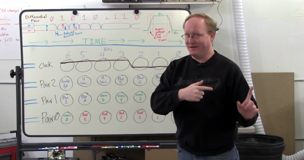
Fans of [Ben Heck] know that he has a soft spot for pinball machines and his projects that revolve around that topic tend to be pretty epic. This is a good example. At a trade show he saw an extra-wide format LCD screen which he thought would be perfect on a pinball build. He found out it’s a special module made for attaching to your car’s sun visor. The problem is that it only takes composite-in and he wanted higher quality video than that offers. The solution: reverse engineer the LCD protocol and implement it in an FPGA.

This project is a soup to nuts demonstration of replacing electronics drivers; the skill is certainly not limited to LCD modules. He starts by disassembling the hardware to find what look like differential signaling lines. With that in mind he hit the Internet looking for common video protocols which will help him figure out what he’s looking for. A four-channel oscilloscope sniffs the signal as the unit shows a blue screen with red words “NO SIGNAL”. That pattern is easy to spot since the pixels are mostly repeated except when red letters need to be displayed. Turns out the protocol is much like VGA with front porch, blanking, etc.

With copious notes about the timings [Ben] switches over to working with a Cyclone III FPGA to replace the screen’s stock controller. The product claims 800×234 resolution but when driving it using those parameters it doesn’t fill the entire screen. A bit more tweaking and he discovers the display actually has 1024×310 pixels. Bonus!

It’s going to take us a bit more study to figure out exactly how he boiled down the sniffed data to his single color-coded protocol sheet. But that’s half the fun! If you need a few more resources to understand how those signals work, check out one of our other favorite FPGA-LCD hacks.

Continue reading “Reverse Engineer Then Drive LCD With FPGA”

CAMdrive

CAMdrive Is An Open Source Time-lapse Photography Controller

[Nightflyer] has been working on an open source project he calls CAMdrive. CAMdrive is designed to be a multi-axis controller for time-lapse photography. It currently only supports a single axis, but he’s looking for help in order to expand the functionality.

You may already be familiar with the idea of time-lapse photography. The principal is that your camera takes a photo automatically at a set interval. An example may be once per minute. This can be a good way to get see gradual changes over a long period of time. While this is interesting in itself, time-lapse videos can often be made more interesting by having the camera move slightly each time a photo is taken. CAMdrive aims to aid in this process by providing a framework for building systems that can pan, tilt, and slide all automatically.

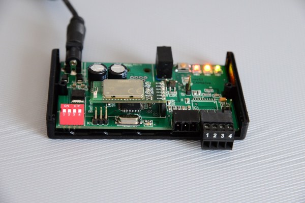
The system is broken out into separate nodes. All nodes can communicate with each other via a communication bus. Power is also distributed to each node along the bus, making wiring easier. The entire network can be controlled via Bluetooth as long as any one of the nodes on the bus include a Bluetooth module. Each node also includes a motor controller and corresponding motor. This can either be a stepper motor or DC motor.

The system can be controlled using an Android app. [Nightflyer’s] main limitation at the moment is with the app. He doesn’t have much experience programming apps for Android and he’s looking for help to push the project forward. It seems like a promising project for those photography geeks out there. Continue reading “CAMdrive Is An Open Source Time-lapse Photography Controller”

hassler_pcb

Annoy Your Enemies With The Hassler Circuit

[Craig] recently built himself a version of the “hassler” circuit as a sort of homage to Bob Widlar. If you haven’t heard of Bob Widlar, he was a key person involved in making analog IC’s a reality. We’ve actually covered the topic in-depth in the past. The hassler circuit is a simple but ingenious office prank. The idea is that the circuit emits a very high frequency tone, but only when the noise level in the room reaches a certain threshold. If your coworkers become too noisy, they will suddenly notice a ringing in their ears. When they stop talking to identify the source, the noise goes away. The desired result is to get your coworkers to shut the hell up.

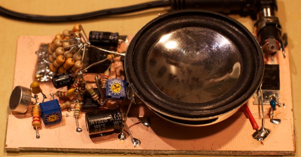
[Craig] couldn’t find any published schematics for the original circuit, but he managed to build his own version with discrete components and IC’s. Sound first enters the circuit via a small electret microphone. The signal is then amplified, half-wave rectified, and run through a low pass filter. The gain from the microphone is configurable via a trim pot. A capacitor converts the output into a flat DC voltage.

The signal then gets passed to a relaxation oscillator circuit. This circuit creates a signal whose output duty cycle is dependent on the input voltage. The higher the input voltage, the longer the duty cycle, and the lower the frequency. The resulting signal is sent to a small speaker for output. The speaker is also controlled by a Schmitt trigger. This prevents the speaker from being powered until the voltage reaches a certain threshold, thus saving energy. The whole circuit is soldered together dead bug style and mounted to a copper clad board.

When the room is quiet, the input voltage is low. The output frequency is high enough that it is out of the range of human hearing. As the room slowly gets louder, the voltage increases and the output frequency lowers. Eventually it reaches the outer limits of human hearing and people in the room take notice. The video below walks step by step through the circuit. Continue reading “Annoy Your Enemies With The Hassler Circuit”

The Art Of Electronics, Third Edition

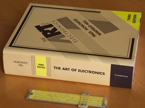
For any technical domain, there is usually one book held up above all others as the definitive guide. For anyone learning compilers, it’s the dragon book. For general computer science, it’s the first half of [Knuth]’s The Art of Computer Programming. For anyone beginning their studies of electrons and silicon, it’s [Horowitz & Hill]’s The Art of Electronics. This heady tome has graced workbenches and labs the world over and is the definitive resource for anything electronica. The first edition was published in 1980, and the second edition was published in 1989. Now, finally, the third edition is on its way.

The new edition will be released on April 30, 2015 through Cambridge University Press, Amazon, and Adafruit. In fact, [PT] over at Adafruit first announced the new edition on last night’s Ask An Engineer show. [Ladyada] was actually asked to provide a quote for the cover of the new edition, an incredible honor that she is far too humble about.

The latest edition is about 300 pages longer than the second edition. It is thoroughly revised and updated, but still retains the casual charm of the original. Real copies do not exist yet, and the only critical review we have so far is from [Ladyada]. There will be few surprises or disappointments.

Continue reading “The Art Of Electronics, Third Edition”

Fail Of The Week: Electrically Effective Emulators Exceed Enclosure, Enrage Engineer

After a few years of on and off development, [Steve] from Big Mess ‘o Wires completed work on a floppy disk drive emulator for older Macs such as the Plus. The emu plugs into the DB-19 port on the Mac and acts just like a 3.5″ floppy, using an SD card to store the images. He’s been selling the floppy emus for about the last year, and assembled the first several scores of them himself. At some point, he enlisted a board house to make them, and as of November 2014, he’s had enclosures available in both clear acrylic and brown hardboard.

[Steve] recently ran out of emu stock, so it was time to call up the board house and get some more assembled. After waiting six weeks, they finally showed up. But in spite of [Steve]’s clear and correct instructions, all 100 boards are messed up. One resistor is missing altogether, and they transposed a part between the extension cable adapter board, connecting it directly to the emu main board. But get this: the boards still work electrically. They don’t fit in the housings, however, and the extension cables are useless. After explaining the situation, the board house agreed to cook up a new batch of boards, which [Steve] is waiting patiently to receive.


2013-09-05-Hackaday-Fail-tips-tileFail of the Week is a Hackaday column which runs every Wednesday. Help keep the fun rolling by writing about your past failures and sending us a link to the story — or sending in links to fail write ups you find in your Internet travels.

SPATA: Shaving Seconds And Saving Brainpower Whilst 3D-modeling

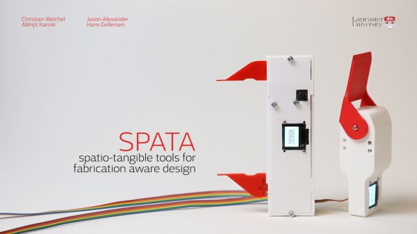
If you’ve spent some late nights CADing your next model for the 3D printer, you might find yourself asking for a third hand: one for the part to-be-modeled, one for the tool to take measurements, and one to punch the numbers into the computer. Alas, medical technology just isn’t there yet. Luckily, [Christian] took a skeptical look at that third hand and managed to design it out of the workflow entirely. He’s developed a proof-of-concept tweak on conventional calipers that saves him time switching between tools while 3D modeling.

His build [PDF] is fairly straightforward: a high-resolution digital servo rests inside the bevel protractor while a motorized potentiometer, accelerometer, and µOLED display form the calipers. With these two augmented devices, [Christian] can do much more than take measurements. First, both tools are bidirectional; not only can they feed measurement data into the computer with the push of at button, both tools can also resize themselves to a dimension in the CAD program, giving the user a physical sense of how large or small their dimensions are. The calipers’ integrated accelerometer also permits the user to perform CAD model orientation adjustments for faster CAD work.

How much more efficient will these two tools make you? [Christian] performs the same modeling task twice: once with conventional calipers and once with his tools. When modeling with his augmented device, he performs a mere 6 context switches, whereas conventional calipers ratchet that number up to 23.

In a later clip, [Christian] demonstrates a design workflow that combines small rotations to the model while the model is sculpted on a tablet. This scenario may operate best for the “if-it-looks-right-it-is-right” sculpting mindset that we’d adopt while modeling with a program like Blender.

Of course, [Christian’s] calipers are just a demonstration model for a proof-of-concept, and the accuracy of these homemade calipers has a few more digits of precision before they can rival their cousin on your workbench. (But why let that stop you from modifying the real thing?) Nevertheless, his augmented workflow brings an elegance to 3D modeling that has a “clockwork-like” resonance of the seasoned musician performing their piece.

[via the Tangible, Embedded, and Embodied Interaction Conference]

Continue reading “SPATA: Shaving Seconds And Saving Brainpower Whilst 3D-modeling”