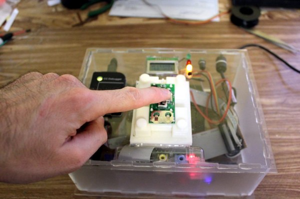
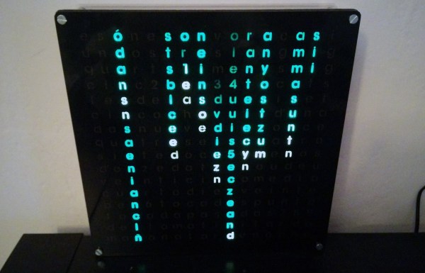
[Xose] already built his own versions of [Philippe Chrétien’s] Fibonacci Clock and [Jeremy Williams’s] Game Frame, and while doing so he designed a nice little PCB. It’s powered by an ATmega328p, features an RTC with backup battery, an SD-card socket, and it’s ready to drive a bunch of WS2812Bs aka NeoPixels. Since he still had a few spare copies of his design in stock, his new word clock is also driven by this board.
“I wasted a weekend learning why elemental bismuth is not commonly used for metal parts.“
It’s a fair assessment of his time spent growing unspectacular bismuth crystals, casting a bismuth cylinder that cracked, and machining bismuth only to be left with a very rough finish. But even though he admits the exercise was unsuccessful, he does provide us with a fascinating look at the physical properties of the element.
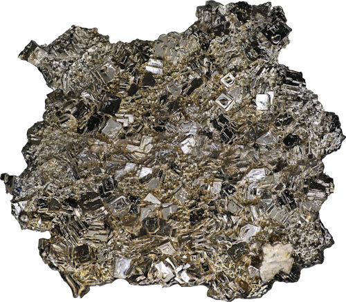
This is what [David] wanted to make. Alchemist-hp + Richard Bartz with focus stack. (Own work) [CC BY-SA 3.0], via Wikimedia Commons
Bismuth is one of those elements you pass by in your school chemistry lessons, it has applications in machining alloys and as a lead replacement but most of us have never knowingly encountered it in the real world. It’s one of the heavy metals, below antimony and to the right of lead on the Periodic Table. Curious schoolchildren may have heard that like water it expands on solidifying or that it is diamagnetic, and most of us have probably seen spectacular pictures of its crystals coated in colourful iridescent oxides.
It was a Hackaday story about these crystals that attracted [David] to the metal. It has a low enough melting point – 271.5 °C – that it can be liquified on a domestic stove, so mindful of his marital harmony should he destroy any kitchen appliances he bought a cheap electric ring from Amazon to go with his bismuth ingot. and set to work.
His first discovery was that cheap electric rings outdoors aren’t very effective metallurgy furnaces. Relocating to the kitchen and risking spousal wrath, he did eventually melt his bismuth and pick off the top layer once it had resolidified, to reveal some crystals.
These are the bismuth crystals he made.
Unfortunately for him, instead of spectacular colors and huge crystals, the sight that greeted him was one of little brilliance. Small grey crystals with no iridescence. It seems the beautiful samples are made by a very slow cooling of the liquid bismuth, followed by a quick pouring off of the remaining molten metal. Future efforts, he assures us, will involve sand-insulated molds and careful temperature monitoring.
Undeterred, he continued with his stock of bismuth and embarked on the creation of a cylinder. Early efforts with a clay mold resulted in cracked cylinders, so in desperation he cast the entirety of the metal in an aluminium baking tray and cut the resulting ingot to a rough piece of stock for turning.
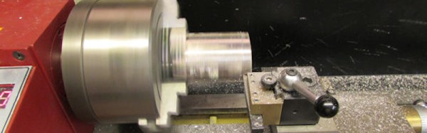
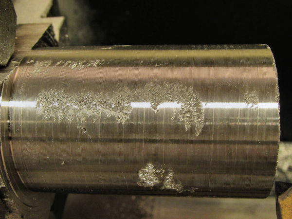
Poor finish on machined bismuth.
With the bismuth in the lathe, he then came face to face with what he alluded to in his conclusion above, why machined bismuth parts aren’t something you’ll encounter. His cylinder came out with significantly rough patches on the surface, because bismuth is both crystalline and brittle. He suggests improvements could be made if the metal could be solidified with fewer crystals, but it’s obvious that elemental bismuth on its own is not a winner in the turning stakes.
We suggest you take a look at [David]’s write-up. It may be presented as a Fail of The Week here, but in fact it’s more of a succession of experiments that didn’t work than an unmitigated disaster. The result is an interesting and well-documented read that we’re sure most Hackaday readers will gain something from.
Fail of the Week is a Hackaday column which celebrates failure as a learning tool. Help keep the fun rolling by writing about your own failures and sending us a link to the story -- or sending in links to fail write ups you find in your Internet travels.
In our final installment of Tools of the Trade (with respect to circuit board assembly), we’ll look at how the circuit board is tested and programmed. At this point in the process, the board has been fully assembled with both through hole and surface mount components, and it needs to be verified before shipping or putting it inside an enclosure. We may have already handled some of the verification step in an earlier episode on inspection of the board, but this step is testing the final PCB. Depending on scale, budget, and complexity, there are all kinds of ways to skin this cat.
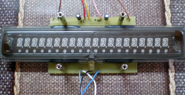
There’s no shortage of clock projects, but [niq_ro] has his own take using a vacuum fluorescent display (VFD), and Arduino, and a pair of MAX6921 ICs. Those chips are made to drive a VFD, and the use of two of the ICs required a bit of work. The Arduino is not a great time keeper, so the clock also uses a DS3231 clock module and a humidity and temperature sensor.
The clock is in Romanian, although there are some options for different text. You can find the code on GitHub and can see the result in the video below.
Imagine this: you come home after a day at work. As you open the door, your nose is the first alert that something is very, very wrong. Instead of the usual house smell, your nose is assaulted with the distinctive aroma that means your dog had an accident. The smell is stronger though — as if Fido brought over a few friends and they all had a party. Flipping the lights on, the true horror is revealed to you. This was a team effort, but only one dog was involved.
At some point after the dog’s deed, Roomba, your robot vacuum, took off on its scheduled daily run around the house. The plucky little robot performed its assigned duties until it found the mess. The cleaning robot then became an agent of destruction, smearing a foul smelling mess throughout the space it was assigned to clean. Technology sometimes has unintended consequences. This time, your technology has turned against you.
This scene isn’t a work of fiction. For a select few families, it has become an all too odoriferous reality just begging for a clever fix.
Amateur radio has a couple of sweet allocations in the VHF bands, but because the signals don’t reflect off the ionosphere like shortwave signals, the use is limited basically to line-of-sight. One workaround is to use a repeater with a tall antenna, but that requires a lot of infrastructure or a mountainside lair.
What if you could just fly your antenna up in a drone? Well, for starters, you’d run out of batteries pretty quickly unless you could power it remotely. And if you try to tether it, the supply wires end up being too heavy to lift. Or do they?!?!
[Andrew Peterson] was looking for a way to indulge in his retro gaming passions in a more contemporary manner. His 3D NES emulator “N3S” for Windows brings Nintendo classics to the HoloLens, turning pixels into voxels, and Super Mario into an augmented reality gingerbread man.
To run NES games on the HoloLens, [Andrew’s] emulator uses the Nestopia libretro core. Since AR glasses cry for an augmentation of the game itself, the N3S re-emulates the NES’ picture processing unit (PPU), allowing it to interpret a Nintendo game’s graphics in a 3D space. [Andrew] also put together a comprehensive explanation of how the original Nintendo PPU works, and how he re-implemented it for the HoloLens.
The current version of the N3S PPU emulator automatically generates voxels by simply extruding the original pattern data from the game’s ROM, but [Andrew] is thinking about more features. Users could sculpt their own 3D versions of the original graphic elements in an inbuilt editor, and model sets could then be made available in an online database. From there, players would just download 3D mods for their favorite games and play them on the HoloLens.
According to [Andrew], the emulator reaches the limits of what the current pre-production version of the HoloLens can render fluently, so the future of this project may depend on future hardware generations. Nevertheless, the HoloLens screen capture [Andrew] recorded makes us crave for more augmented retro gaming. Enjoy the video!
![This is what [David] wanted to make. Alchemist-hp + Richard Bartz with focus stack. (Own work) [CC BY-SA 3.0], via Wikimedia Commons](https://hackaday.com/wp-content/uploads/2016/08/bi-crystal.jpg)
 Fail of the Week is a Hackaday column which celebrates failure as a learning tool. Help keep the fun rolling by writing about your own failures and