VR Telepresence Tank From Raspberry Pi, Google Cardboard, And Xbox Controller

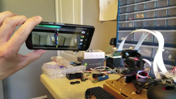
It’s great to see different kinds of hardware and software tossed into a project together, allowing someone to mix things that don’t normally go together into something new. [Freddy Kilo] did just that with a project he calls his VR Robot Tank. It’s a telepresence device that uses a wireless Xbox controller to drive a tracked platform, which is itself headed by a Raspberry Pi.

The Pi has two cameras on a pan-tilt mount, and those cameras are both aimed and viewed via a Google Cardboard-like setup. A healthy dose of free software glues it together, allowing things like video streaming (with U4VL) and steering via the wireless controller (with xboxdrv). A bit of fiddling was required for some parts – viewing the stereoscopic cameras for example is done by opening and positioning two video windows just right so as to see them through the headset lenses. It doesn’t warp the image to account for the lens distortion in the headset, and the wireless range might be limited, but the end result seems to work well enough.

The tank is driven with the wireless controller while a mobile phone mounted in a headset lets the user see through the cameras; motion sensing in the phone moves those cameras whenever you move your head to look around. Remote Control hobbyists will recognize the project as doing essentially the same job as FPV setups for model aircraft (for example, Drone Racing or even Snow Sleds) but this project uses a completely different hardware and software toolchain. It demonstrates the benefits of having access to open tools to use as virtual “duct tape”, letting people stick different things together to test a concept. It proves almost anything can be made to work if you have a willingness to fiddle!

Continue reading “VR Telepresence Tank From Raspberry Pi, Google Cardboard, And Xbox Controller”

Now You’re Printing With Water

How do you earn a place in a flower festival with a handful of Arduinos and a 3D printer? By building a water curtain that draws flowers. That’s exactly what Tecnoateneu Vilablareix, a hacking community in Spain did. They built this project specifically for Temps de Flors, a popular annual gathering in Girona, Spain. More than just a flower festival, the event opens gardens and courtyards of culturally importance to the general public that are closed the rest of the year.

A pile of nozzle fail.

The water curtain uses four Arduino Nanos to control the valves, which work in pairs to draw flowers, words, and patterns. A Mega provides a wifi connection  to receive commands. Over 16 continuous days worth of print time went into the 128 valves and 64 nozzles that make up the water curtain. It took the group around 24 iterations to get the valve design just right—they have to be able to shut off quickly.

There’s an eight-video playlist after the break and a special video that shows how much we love pandering. Most of the ones in the playlist are quite short and demonstrate the final version of the water curtain. Others show the valve testing. The last is a time-lapse of the group setting it up at the festival. If you’re in the area, the festival runs until May 15th.

Now that you’re in the mood for computer-controlled water shows, here is a fountain controlled with a RaspPi.

Continue reading “Now You’re Printing With Water”

Hackaday Prize Entry: Powering A Pi From A Battery

Knocking a microcontroller into sleep mode and waking it up on demand or in intervals is common practice in many low power applications, enabling devices to stay in operation for years on a single coin cell battery. Since there are tons of applications where you might want to do similar things with a Raspberry Pi, [Patrick Van Oosterwijck] created the LiFePO4wered/Pi. The module that snaps on to eight GPIO pins of a Pi, extending it by a long life LiFePO4 battery, a charging regulator, and a proper power management. Obviously, it also makes a great UPS.

lifepo_pcbs[Patrick] realized this project by expanding his already available and equally useful LiFePO4wered/USB charging regulator module by a low power MSP430G2131 microcontroller and a load switch. A daemon on the Raspberry Pi speaks to the module over I2C, allowing you to schedule a wake-up timer, let your Pi autoboot after a power outage or just read out the current battery voltage through a command line tool. Once the Pi is safely shut down, the microcontroller will also go to sleep, resulting in a standby current of 8 uA for the whole system. Together with the 500 mAh LiFePo4 cell, that’s theoretically low enough to send your Pi-ncess into a seven-year-long sleep.

LiFePO4wered/Pi is not only good for sleeping, though. [Patrick’s] runtime tests show, that the 500 mAh cell will power a Raspberry Pi Zero and a WiFi dongle for about two hours. Because the Raspberry Pi and many USB peripherals won’t complain when only 3.2 V are present on the VBUS, [Patrick] was able to squeeze out even more runtime by dismissing the boost converter from the design and driving the Pi directly from the battery voltage. If that worries you, you can either read a detailed explanation on why that works so well or just have a look at the more compliant 5 V version.

lifepo_time_laps_cameraEventually, [Patrick] used his module to create a Raspberry Pi time-lapse camera. A little script lets the Pi take a picture on boot up, set a wake-up timer and go back to sleep again. Safely enclosed in a waterproof electric box and deployed into the wild, the camera took 120 pictures on a single charge.

We’re sure the module will find it’s way into many cool projects and we’re counting the hours until we can get one in [Patrick’s] tindie store. Until then, enjoy the time-lapse video:

The HackadayPrize2016 is Sponsored by:


Concrete Table Just The Way You Like It

You need a coffee table, you need a dinner table. Do you really need two tables? [Shua] thinks the answer is “no”. That’s why he built this swinging countersink table out of concrete and a aluminum.

He started by making a simple half-scale prototype. Then a larger one. Through these explorations he learned how the table would be made, what kind of weight it needed, and how the mechanics needed to be constructed for the most stable table top.

Next he designed the final table in Autodesk Revit. This is software traditionally used for architecture. Since the table was to be made from concrete Revit’s useful set of concrete tools were useful for this project.

Most of the construction process was pretty standard. However, the use of CNC’d pink insulation as a mold for the concrete was interesting. The foam is closed cell, so it worked fine and gave a nice finish. The assembly was finished with a glass top and a carpeted base that contained a surge suppressor and two outlets. The table can be seen swinging between two positions in a video after the break.

Continue reading “Concrete Table Just The Way You Like It”

Hand drawing and laser etching - rocket

Converting Kids’ Hand-Drawings To G-Code

[Martin Raynsford] wrote a program that converts a black-and-white 2D image to G-code so that his laser printer could then etch the image. Not satisfied with just that, he used his laser printer to make a scanner that consists of a stand for his webcam and a tray below it for positioning the paper just right. The result was something he took to a recent Maker Faire where many kids drew pictures on paper which his system then scanned and laser etched.

Screenshot of Martin's scanning and G-code maker program
Martin’s scanning and G-code maker program

[Martin’s] program, written in C#, does the work of taking the image from the webcam using OpenGL and scanning it line by line looking for pixels that surpass a contrast threshold. For each suitable pixel the program then produces G-code that moves the laser to the corresponding coordinate and burns a hole. Looking at the source code (downloadable from his webpage) it’s clear from commented-out code that he did plenty of experimenting, including varying the laser burn time based on the pixel’s brightness.

While it’s a lot of fun writing this code as [Martin] did, after the break we talk about some off-the-shelf ways of accomplishing the same thing.

Continue reading “Converting Kids’ Hand-Drawings To G-Code”

TV Stick Out-Raspberries Raspberry Pi

Android-based TV sticks should be in more projects. They are readily available and inexpensive. They have a lot of horsepower for the price, and they can even boot a mainline Linux kernel, unlike some single-board computers we know. They’re smaller than the Pi Zero, so they’ll fit almost anywhere.

The one thing they don’t have, though, is I/O. Sure, it’s got a USB port, but that’s just about it. [Necromant] considered these problems and created a carrier board that fixes all that.

  • On-board 3A DC-DC. You can power the whole thing with anything from 7 to 24 volts DC
  • A 4-Port USB hub
  • An ATtiny 2313, connected to the hub via the V-USB stack
  • 2 USB ports on the back, with power control via GPIO lines
  • One USB port on the front (with power always on)
  • 3 relays
  • Fits a common anodized aluminum enclosure

The ATtiny code is on GitHub and allows for full I/O control, saving the state of the pins in EEPROM, and providing up to eight channels of servo control. The device connects through the USB port (consuming one port on the hub).

Repurposing consumer gear for embedded service is nothing new. We’ve seen it with phones. We’ve even seen remotes used as a mouse. But this is such a nice template for adding cheap and easy computing power to your projects that we’re surprised we don’t see it more often. Why aren’t you hacking a TV stick into your projects?

Mike Szczys Ends 8-Bit Vs 32-Bit Holy War!

If you’ve read through the comments on Hackaday, you’ve doubtless felt the fires of one of our classic flame-wars. Any project done with a 32-bit chip could have been done on something smaller and cheaper, if only the developer weren’t so lazy. And any project that’s squeezes the last cycles of performance out of an 8-bit processor could have been done faster and more appropriately with a 32-bit chip.

bits_argument

Of course, the reality for any given project is between these two comic-book extremes. There’s a range of capabilities in both camps. (And of course, there are 16-bit chips…) The 32-bit chips tend to have richer peripherals and run at higher speeds — anything you can do with an 8-bitter can be done with its fancier cousin. Conversely, comparatively few microcontroller applications outgrow even the cheapest 8-bitters out there. So, which to choose, and when?

Eight Bits are Great Bits

The case that [Mike] makes for an 8-bit microcontroller is that it’s masterable because it’s a limited playground. It’s a lot easier to get through the whole toolchain because it’s a lot shorter. In terms of debugging, there’s (often) a lot less that can go wrong, letting you learn the easy debugging lessons first before moving on to the truly devilish. You can understand the hardware peripherals because they’re limited.

And then there’s the datasheets. The datasheet for a chip like the Atmel ATMega168 is not something you’d want to print out, at around 660 pages long. But it’s complete. [Mike] contrasts with the STM32F405 which has a datasheet that’s only 200 pages long, but that’s just going over the functions in principle. To actually get down to the registers, you need to look at the programming manual, which is 1,731 pages long. (And that doesn’t even cover the various support libraries that you might want to use, which add even more to the documentation burden.) The point is, simpler is simpler. And if you’re getting started, simpler is better.

Continue reading “Mike Szczys Ends 8-Bit Vs 32-Bit Holy War!”