Hackaday Journal Completes First Review Process, Seeks More Submissions

Congratulations and thank you go to Theodore Yapo for authoring the first paper to complete the peer review process for the Hackaday Journal. You can read the standalone paper here; it will be included in the first volume of the Hackaday Journal officially released later this year.

The Hackaday Journal is an open access, peer reviewed journal that seeks to ensure hard-won domain knowledge is preserved and made available for the benefit of all. Before jumping into Ted’s topic, please take a moment to consider submitting your own paper for the journal.

Paper Submissions Wanted

We have other submissions in the pipleline now but we still need more papers to round out the first volume of the Hackaday Journal. Please consider authoring a paper on any creative research, engineering, or entertaining discovery in the areas of interest to the Hackaday community. The full name of our journal is the Hackaday Journal of What You Don’t Know — it will be a tome of infinite appeal to any who seek to broaden their minds in the engineering space. But for that to happen we need you to share your knowledge.

We are in an age of unparalleled opportunity for individuals and small teams to make interesting discovery. You should not need to be working on a degree to have your findings published, but of course students and faculty are encouraged to submit their papers. Do not hesitate to get in touch with us about topics you want to write about.

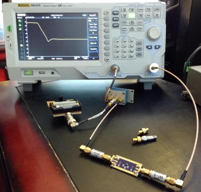
Scalar Network Analyzer Leakage Correction by Theodore Yapo

Low-pass filter being tested by a Rigol DSA-815 using the phase shifting correction technique

The title of Ted’s paper is a mouthful and the subject material wades into radio frequency knowledge with gusto. We applaud him, and the peer reviewers, for the attention to detail while moving toward publication.

In his work, Ted finds an interesting opportunity to get more performance out of relatively inexpensive bench equipment used to characterize RF components. This task is often reserved for Vector Network Analyzers (VNA) but with a heafty price tag these tools aren’t available to everyone. Spectrum Analyzers with Tracking Generators (SA/TG) have come onto the market, but especially with early versions, there is a leakage problem that causes inaccuracy. Ted found a simple technique that can correct for the leakage.

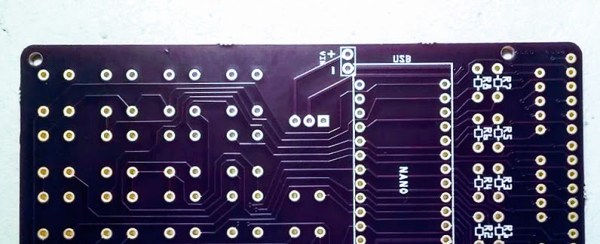
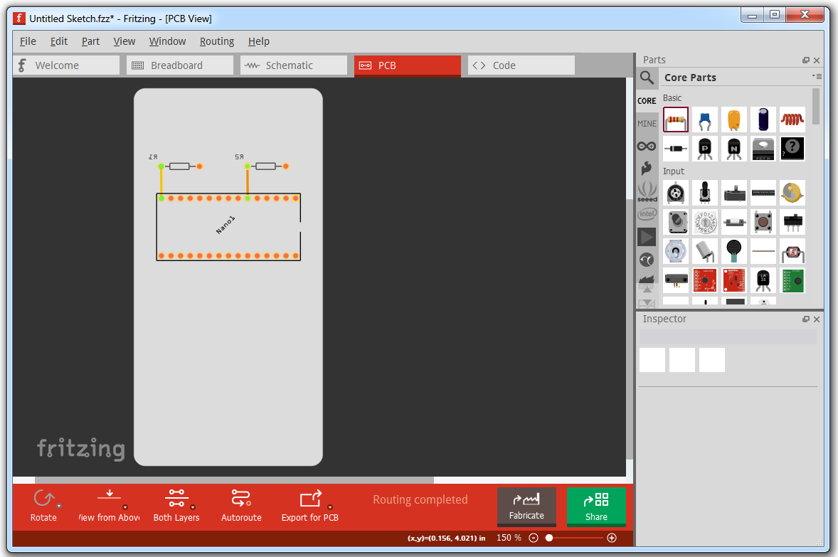
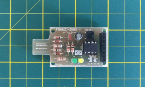
The solution is based on phase shifting the measurement. Starting with a properly calibrated machine, Ted uses a small board he built to electronically shift the phase of the Tracking Generator where the leakage is a problem. The signal is first measured, then measured again with a phase shift of 180 degrees. This effectively cancels out the error while preserving the signal being measured.

This paper goes into great technical detail in the RF domain. It is worth noting that the Hackaday Journal is open to discovery on multiple topics and levels of complexity. Don’t let what you think is a simple, useful idea go unpublished. We’re interested in a wide range of the simple, the obscure, and the frighteningly technical as long as the ideas of both novel and well supported.

This is Your Journal

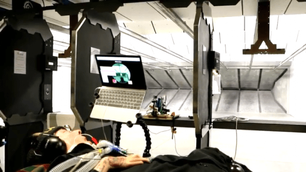
You, yes you reading this right now, embody a movement of inventive and curious people working both inside and outside of formal academic structures. This is our time to contribute to the knowledge base of humanity. Pour yourself a refreshing beverage, saddle up your headphones, crack those knuckles, and let the writing process begin. Let us now what we don’t know. Submit your paper now.

ESP8266 Keeps Tabs On The Kid’s Tablets

Assuming you have a child and it’s no longer womb-bound, there’s a fairly high chance they’ve already had some experience with the glowing beauty that is the LCD display; babies of only a few months old are often given a tablet or smartphone to keep them occupied. But as the child gets to the age where they are capable of going outside or doing something more constructive, staring slack-jawed and wide-eyed at their tablet becomes a concern for many parents.

[Richard Garsthagen] is one such parent. He wanted a way to monitor and control how much time his children were using their iPad, so he came up with an automated system based on the ESP8266. Not only does it keep track of how long the tablet is being used, it even includes a reward system which allows the parent to add extra usage time for good behavior.

At the most basic level, the device is a sort of “holster” for the child’s tablet. When the tablet is placed in the slot, it presses a microswitch at the bottom of the cavity which stops the timer. When the switch is open, the LED display on the front of the device counts down, and the ESP8266 pushes notifications about remaining time to the child’s device via IFTTT.

Time can be added to the clock by way of RFID cards. The cards are given out as a reward for good behavior, completion of chores, etc. The child only needs to pass the card in front of the system to redeem its value. Once the card has been “spent”, the parent can reset it with their own special card.

It’s a very slick setup, making perfect use of the ESP8266. Reading the RFID cards, updating the timer, and using IFTTT’s API keeps the little board quite busy; [Richard] says it’s completely maxed out.

You might be wondering what happens when the clock reaches zero. Well, according to the video after the break…nothing. Once the time runs out, a notification simply pops up on the tablet telling them to put it away. Some might see this as a fault, but presumably it’s the part of the system where humans take over the parenting and give the ESP8266 a rest.

This isn’t the first time we’ve seen a microcontroller used to get the little hackers on schedule. At least (so far) none of them have gone full Black Mirror and started tracking when the kiddos are watching it.

Continue reading “ESP8266 Keeps Tabs On The Kid’s Tablets”

Open Source DIY Printers Are Alive And Well: What We Saw At ERRF 18

If you follow the desktop 3D printer market, it probably won’t surprise you to hear that nearly every 3D printer on display at the inaugural East Coast RepRap Festival (ERRF) was made in China. Even Printrbot CEO Brook Drumm had to admit that this was the year his company may finally bite the bullet and begin selling a branded and customized printer built overseas.

When you can get a decent (but let’s be clear, not great) 3D printer for $200 USD, it’s no surprise that American and European manufacturers are having a hard time staying competitive. But not everyone is seduced by low-cost printers. They know they could buy a decent printer for a couple hundred bucks, but for them that’s not the point. Some hackers are just as (if not more) interested in designing and building the machines than they are churning out little plastic boats with the finished product.

Luckily for us, these are also the type of folks who document their builds and make all their collected information and design files available for others under an open source license. Such builders exemplify the true spirit of the RepRap movement, and we’re happy to report that in a sea of imported printers, there were several interesting home built open source printers.

Whether you want to build your own copy of one of these machines, or simply get inspired by some of the ideas their creators had, these machines are physical proof that just because you can order a cheap 3D printer on eBay right now doesn’t mean you have to.

Continue reading “Open Source DIY Printers Are Alive And Well: What We Saw At ERRF 18”

Tattoo Your 3D Prints With Velocity Painting

Just when it seems like we’ve juiced all the creative potential out of our 3D printers, a bold new feature lands on the table. Enter Velocity Painting, a concept brought to life by [Mark Wheadon] that textures our 3D prints with greyscale images.

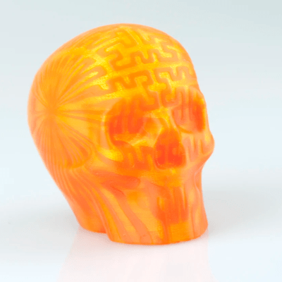
At its core, the technique is straightforward: skin an image onto a 3D print by varying the print speed in specific locations and, thereby, varying just how much plastic oozes out of the nozzle. While the concept seems simple, the result is stunning.

Velocity Painting opens up new ways of expression on top of an existing print with all the skinning opportunities. Imagine adding a texture for realism like this rook that’s been patterned with a brick layout, or imagine an aesthetic embellishment like the flames on [Mark’s] dragon print.

The results speak for themselves, and the growing number of users are proving it. Head on over to the gallery to indulge yourself in this delightful oozing aesthetic that’s sure to turn a few heads.

[Mark Wheadon’s] hack takes the mechanics of how we print and adds another creative tuning knob. If you’re looking for other embellishments for your prints, have a look at [David Shorey’s] work on texturizing fabrics.

Shooting For The First Time With Help From A Raspberry Pi

Like many people, [Mike] has a list of things he wants to do in life. One of them is “fire a gun with a switch,” and with a little help from some hacker friends, he knocked this item off last weekend.

For those wondering why the specificity of the item, the backstory will help explain. [Mike] has spinal muscular atrophy, a disease that was supposed to end his life shortly after it began. Thirty-seven years later, [Mike] is still ticking items off his list, but since he only has voluntary control of his right eyebrow, he faces challenges getting some of them done. Enter [Bill] and the crew at ATMakers. The “AT” stands for “assistive technologies,” and [Bill] took on the task of building a rig to safely fire a Glock 17 upon [Mike]’s command.

Before even beginning the project, [Bill] did his due diligence, going so far as to consult the Bureau of Alcohol, Tobacco, and Firearms (ATF) and arranging for private time at a local indoor gun range. The business end of the rig is a commercially available bench rest designed to control recoil from the pistol, which is fired by a servo connected to the trigger. The interface with [Mike]’s system is via a Raspberry Pi and a Crikit linked together by a custom PCB. A PiCam allowed [Mike] to look down the sights and fire the gun with his eyebrow. The videos below show the development process and the day at the range; to say that [Mike] was pleased is an understatement.

We’re not sure what else is on [Mike]’s list, but we see a lot of assistive tech projects around here — we even had a whole category of the 2017 Hackaday Prize devoted to them. Maybe there’s something else the Hackaday community can help him check off.

Continue reading “Shooting For The First Time With Help From A Raspberry Pi”

How To Design Custom Shaped Boards In Fritzing

If you’re looking to get started in designing a few PCBs, you could use one of the many software packages that allow you to create a PCB quickly, easily, and with a minimum amount of fuss. You could also use Fritzing.

Fritzing is terribad and you shouldn’t use it, but that doesn’t mean you still can’t abuse Fritzing to make it do what you want. [Arduino Enigma] recently posted a tutorial on how to design custom PCB shapes for Fritzing. Yes, Fritzing is no longer limited to rectangular PCBs with sharp corners. You can make PCBs in any shape with Fritzing, provided you spend a few hours futzing about with Inkscape.

The goal for this project was to create a rectangular board without any sharp corners for [Arduino Enigma]’s Sinclair Scientific Calculator Emulator. Fritzing can make a board in the shape of a rectangle, in fact, that’s all it can do, but [Arduino Enigma] wanted a rectangle with radiused corners. After hours of work, we have the writeup on how to do it.

The imported board, with 3mm radiused corners.

The process to create a custom-shaped board, in this case, a rectangle with a 3mm radius on the corners, is simple. First, draw a rectangle of the desired shape, then draw even more rectangles as a sublayer of the current layer. Fritzing requires the layer ID to be named ‘board’, ‘silkscreen’ and ‘silkscreen0’, but this cannot be changed in Inkscape itself — you’ll need to edit the file with a text editor. After creating three layers, each containing the shape you want, simply trim the size of the page to the size of the board. Save the file, edit the file in a text editor, and click save. Launch Fritzing, load an image file, and select the SVG you’ve been working on. In just twenty or thirty quick steps, you too can import any shape you can imagine into Fritzing.

There is one pain point to this process. Editing the layer name manually with a text editor pushes this Fritzing hack from a baroque workaround into something that makes us all question the state of Open Source standards. Unfortunately, this is required because Inkscape does not use layer names as the ID in an SVG file. No, it doesn’t make sense, but that’s just the way it is.

For any other PCB design tool, creating a custom-shaped board is simply a matter of drawing a few lines. Fritzing is different, though. The top copper layer is represented as orange, and the bottom copper layer is yellow, a UI decision that doesn’t make sense, even if you aren’t colorblind. Putting more than two layers of copper on a Fritzing board is impossible. Fritzing is a tool you should avoid for PCB layout. That said, [Arduino Enigma] figured out how to do something in Fritzing that you’re not supposed to be able to do and that’s pretty cool.

The Smaller, Tinier Arduino Platform

While many of the Arduino platforms are great tools for gaining easy access to microcontrollers, there are a few downsides. Price and availability may be the highest on the list, and for those reasons, some have chosen to deploy their own open-source Arduino-compatible boards.

The latest we’ve seen is the Franzininho, an Arduino Gemma-like board that’s based on the ATtiny85, a capable but tiny microcontroller by Atmel in a compact 8-pin configuration. This board has everything the Gemma has, including a built-in LED and breakout pins. One of the other perks of the Franzininho over the Gemma is that everything is based on through-hole components, making the assembly much easier than the surface mount components of the Gemma.

It’s worth noting that while these boards are open source, the Arduinos are as well. It’s equally possible to build your own 100% identical Arduino almost as easily. If you want more features, you can add your own by starting from one of these platforms and do whatever you want with it, like this semi-educational Atmel breakout board.

Thanks to [Clovis] for the tip!