No Caffeine, No Problem: A Hand-Soldered Chip-Scale Package

It’s said that the electronic devices we use on a daily basis, particularly cell phones, could be so much smaller than they are if only the humans they’re designed for weren’t so darn big and clumsy. That’s only part of the story — battery technology has a lot to do with overall device size — but it’s true that chips can be made a whole lot smaller than they are currently, and are starting to bump into the limit of being able to handle them without mechanical assistance.

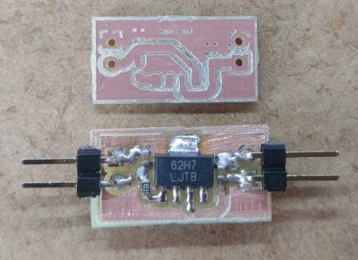
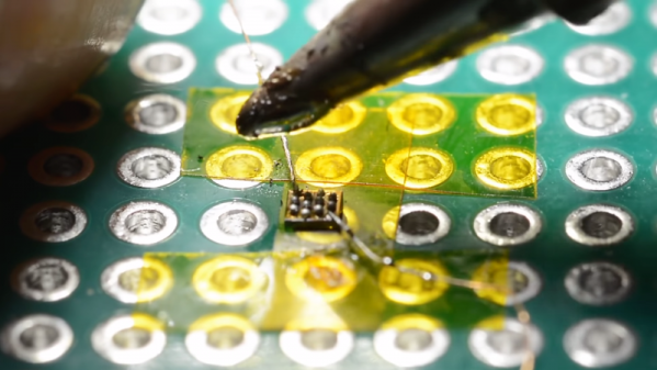
Or perhaps not, if [mitxela]’s hand-soldering of a tiny ball-grid array chip is any guide. While soldering wires directly to a chip is certainly a practical skill and an impressive one at that, this at least dips its toe into the “just showing off” category. And we heartily endorse that. The chip is an ATtiny20 in a WLCSP (wafer-level chip-scale package) that’s a mere 1.5 mm by 1.4 mm. The underside of the chip has twelve tiny solder balls in a staggered 4×6 array with 0.4 mm pitch. [mitxela] tackled the job of soldering this chip to a 2.54-mm pitch breakout board using individual strands from #30 AWG stranded wire and a regular soldering iron, with a little Kapton tape to hold the chip down. Through the microscope, the iron tip looks enormous, and while we know the drop of solder on the tip was probably minuscule we still found ourselves mentally wiping it off as he worked his way across the array. In the end, all twelve connections were brought out to the protoboard, and the chip powers up successfully.

We’re used to seeing [mitxela] work at a much larger scale, like his servo-plucked music box or a portable Jacob’s Ladder. He’s been known to get small before though, too, like with these tiny blinkenlight earrings.

Continue reading “No Caffeine, No Problem: A Hand-Soldered Chip-Scale Package”

Everything You Didn’t Know You Were Missing About Bias Tees

Do you need a bias tee? If you want to put a DC voltage on top of an RF signal, chances are that you do. But what exactly are bias tees, and how do they work?

If that’s your question, [W2AEW] has an answer for you with this informative video on the basics of bias tees. A bias tee allows a DC bias to be laid over an RF signal, and while that sounds like a simple job, theory and practice often deviate in the RF world. The simplest bias tee would have a capacitor in series with the RF input and output to pass AC but block DC from getting out the input, and a DC input with a series inductance to prevent RF from getting into the DC circuit. Practical circuits are slightly more complicated, and [W2AEW] covers all you need to know about how real-world bias tees are engineered. He also gives some use cases for bias tees, from sending DC signals up a feed line to control an antenna tuner or rotator to adding a DC bias to a high-speed serial line.

It’s an interesting circuit, and we learned a lot, which is par for the course with [W2AEW]’s videos. Check out some of his other offerings, like a practical guide to the mysteries of Smith charts, or his visualization of how standing waves work.

Continue reading “Everything You Didn’t Know You Were Missing About Bias Tees”

The Hills Are Alive With The Sound Of Train Whistles

In Northern England, the hills used to be home to steam trains. The trains have long faded into history, but the sound of their whistle is making a brief return. Artist [Steve Messam] has created “Whistle” as part of The Great Exhibition of the North. [Steve] doesn’t cover the installation on his website yet, but there have been a few great articles about it in the local press.

Whistle consists of 16 steam engine whistles around Newcastle. From June 22 to September 9, you can hear the whistles at 1pm. First one whistle sounds, then another, then another after that. In all, 16 whistles are included in the art installation, all controlled by Raspberry Pi computers. The Pi’s were programmed by Nebula Labs. Tech details are slim on this one, but we’re guessing each Pi has a Cellular radio built-in.

The whistles used in this installation aren’t old train whistles. They are brand new cast brass whistles based upon the original steam train sounders. The compressed air available today doesn’t sound exactly like steam though, so the brass whistles were modified to sound more authentic. [Steve’s] idea is to get the whistle as perfect as possible, which will trigger the memories of those who are old enough to have heard the originals.

Want to know more about steam engines? Check out this Retrotechtacular about repairing steam locomotives!

Conquering The Earth With Cron

The GOES-R series of Earth observation satellites are the latest and greatest NASA has to offer. As you might expect, part of the GOES-R job description is imaging Earth at high-resolution, but they also feature real-time lighting monitoring as well as enhanced solar flare and space weather capabilities. Four of these brand new birds will be helping us keep an eye on our planet’s condition into the 2030s. Not a bad way to spend around 11 billion bucks.

To encourage innovation, NASA is making the images collected by the GOES-R satellites available to the public through a collaboration with Google Cloud Platform. [Ben Nitkin] decided to play around with this data, and came up with an interactive website that let’s you visualize the Earth from the perspective of GOES-R. But don’t let those slick visuals fool you, the site is powered by a couple cron jobs and some static HTML. Just as Sir Tim Berners-Lee intended it.

But it’s not quite as easy as scheduling a wget command; the images GOES-R collects are separated into different wavelengths and need to be combined to create a false-color image. A cron job fires off every five minutes which downloads and merges the raw GOES-R images, and then another cron job starts a Python script that creates WebM time-lapse videos out of the images using ffmpeg. All of the Python scripts and the crontab file are available on GitHub.

Finally, with the images merged and the videos created, the static HTML website is served out to the world courtesy of a quick and dirty Python web server. The site could be served via something more conventional, but [Ben] likes to keep overhead as low as possible.

If you want to take the more direct route, we’ve covered plenty of projects focused on pulling down images from weather satellites; from using old-school “rabbit ears” to decoding the latest Russian Meteor-M N2 downlink.

Continue reading “Conquering The Earth With Cron”

MakerbotCNC PCB etcher

Makerbot Printer Reborn As PCB Engraver

Makerbot 3D printers were among the first to hit the market, so it makes sense that old and broken ones now litter the shelves of hackerspaces and home workshops alike. Rather than throw his one out, [Foaly] saw an opportunity to convert it to some sort of CNC machine. Given its lack of inherent rigidity and relatively weak motors, he opted to make a low-impact circuit board engraver which he appropriately calls the MakerbotCNC. We like the thought he put into this project, and it was clearly backed by plenty of experience.

Circuit board etched using MakerbotCNC

Fortunately, his Makerbot Replicator 2 stemmed from a time when MakerBot was more open, meaning he could control the machine using a simple, open library. A little more open software handled his conversion of Gerber files to G-code. First tests drawing with a pen were successful, so he moved on to the carving head. He opted for an inrunner brushless motor to minimize dust getting into the motor but since these motors have a tendency to heat up he had to add fans to cool it. That still didn’t stop the heat from melting and bending his attempt at a 3D printed PLA carriage, so he switched it to a laser-cut MDF board to fix it. Finding the right collet proved tricky but eventually, he found the perfect fit was a collet clutch normally used to couple flex shafts to RC boat motors.

The result, as you can see was worth it. Using shallow passes, he can even cut carbon fiber parts.

While [Foaly] didn’t opt to replace more parts and go for a more powerful CNC, check out this 3D printer to CNC conversion which can cut wood, acrylic, and even aluminum.

Apple Coin Bank Plants The Seed Of Saving

Consider the piggy bank. Behind that innocent, docile expression is a capitalistic metaphor waiting to ruin your fond memories of saving for that BMX bike or whatever else it was that drove home the value of a dollar. As fun as it is to drop a coin in a slot, the act of saving your pennies and learning financial responsibility could be a bit more engaging.

It seems like [gzumwalt] feels the same way. He’s designed a coin bank for his grand-kids that takes a more active role in the deposit process—it straight up eats the things. Put a coin on the platform and the upper half of the apple’s face is pushed open by an arm that pulls the coin inside on its return path.

Continuing with the money-saving theme, [gzumwalt] didn’t use a micro or even a 555. No, the core of this project is a pair of micro lever switches, a small gear motor, and 4.5V DC. When a coin hits the platform, the first switch engages the motor. The motor drives a 3-D printed mechanism modeled after Hoeckens’ linkage, which converts rotational motion to (nearly) straight-line motion. The second switch stops the cycle. Confused? You can sink your teeth into it after the break.

Don’t worry, the kids don’t have to slice up the apple when it’s time to go to the candy store, ’cause there’s a screw-in hatch on the bottom. This is because [gzumwalt] is a wizard of 3-D printing and design. Not convinced? Check out his balloon-powered engine or his runs-on-air plane.

Continue reading “Apple Coin Bank Plants The Seed Of Saving”

Adding Smarts To Dumb Brushed Motors

A big part of the Hackaday Prize this year is robotics modules, and already we’ve seen a lot of projects adding intelligence to motors. Whether that’s current sensing, RPM feedback, PID control, or adding an encoder, motors are getting smart. Usually, though, we’re talking about fancy brushless motors or steppers. The humble DC brushed motor is again left out in the cold.

This project is aiming to fix that. It’s a smart motor driver for dumb DC brushed motors. You know, the motors you can buy for pennies. The motors that are the cheapest way to add movement to any project. Those motors.

The Smart Motor Driver for Robotics allows a DC brushed motor to be controlled by a host microcontroller over I2C, and sends back the speed and direction of the motor. PID is implemented, and the motor can maintain its own speed, independently of a lot of difficult control on the host system.

The guts of this motor controller are made of a PIC 12F microcontroller, a H-bridge motor driver, a Hall-effect sensor, and a neat magnetic encoder disc. Ultimately, this project will simply bolt onto the back of a cheap brushed motor and give it the same capabilities as a fancy servo or stepper. It’s never going to have the same torque or power handling as a beefy NEMA 17 stepper, but sometimes you don’t need that, and a simple brushed motor will do. A great project, and an excellent entry for the Hackaday Prize.