
[Jordan Wills] was tasked by his company, Silicon Labs, to build some Christmas Baubles to give away to co-workers. While the commissioned units were designed to be simple battery and LED affairs, he decided to make one of his own with bells and whistles. His Mario themed Christmas Ornament uses a Silicon Labs FM972 micro controller, capacitive sensing, PWM controlled 8 bit audio, and blinky lights.
The interesting part is some of the construction techniques that he used. The finger-joint style cube is built from circuit boards. Electrical connections between panels were routed using solder wicking copper braid. That’s a interesting trick which we’ll keep in mind along with some of our favorite creative structural uses of PCB.
The top of the cube has four LED’s which light up the Mario “Question Mark” symbols on the four sides of the cube while the base contains all of the electronics. The outside of the base piece was a large copper plane to act as the capacitive sensing element. This meant all electronics needed to be surface mounted with tracks laid out on one side – which posed some layout challenges. Adding the Capacitive sense function was a cinch thanks to support from the in-house design team. PWM output from the micro controller takes care of audio, and the output is routed through a buffer to boost the signal. A bandpass filter then cleans up the PWM output before feeding it to the speaker.
Continue reading “Christmas Bauble Is Neither Spherical Nor Runs Arduino”
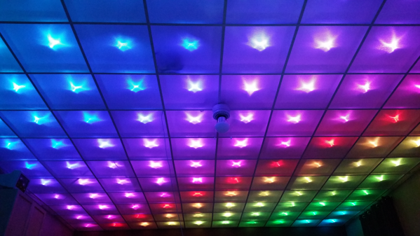
 Disco Floor’s are passé. [dennis1a4] turned them upside down and built an awesome
 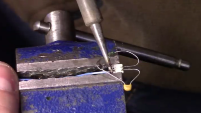 The hard part was wiring up all of the 160 LED pixels. Instead of mounting the 5050 SMD LED’s on PCBs, [dennis1a4] wired them all up “dead bug” style. Each pixel has one LED, a 100nF decoupling capacitor, and 91 ohm resistors in series with the Data In and Data Out pins – these apparently help prevent ‘ringing’ on the data bus. Check the video for his radical soldering method. Each SMD LED was clamped in a machine shop vice, and the other three parts with their leads preformed were soldered directly to the LED pins.

 Another useful utility from [xesscorp] is
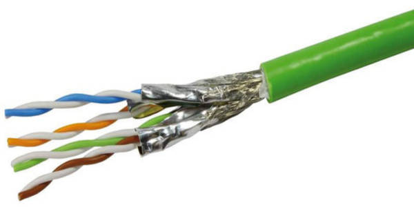
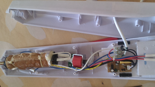
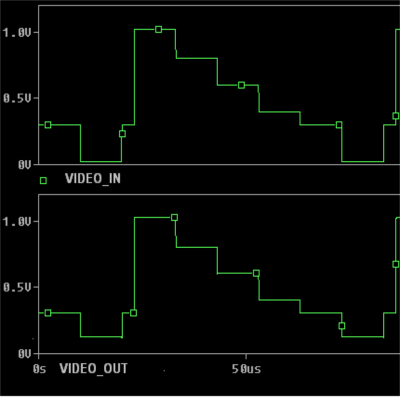 A differential amplifier usually requires a dual-polarity power supply, which may not be available when adding this upgrade to an existing system. To over come this limitation, [Maurizio] uses a bias voltage equal to half of the power supply value. This bias voltage is added to the non-inverting amplifier signal, and subtracted from the inverting amplifier signal. The resultant differential signal is then fed into the twisted pair cable through impedance matching resistors. At the receiving end, a single amplifier receives the differential signals and outputs a signal that corresponds to the original video signal.