Open-Source Thermostat Won’t Anger Your Landlord

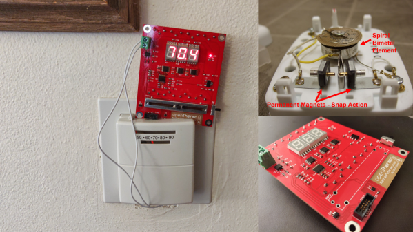
[Nathan Petersen] built a Hackable Open-Source Thermostat to smooth out temperature fluctuations caused by the large hysteresis of the bimetallic strip thermostat in his apartment. While it may be tempting to adjust the “anticipator” to take care of the problem or even replace the bimetallic thermostat with an electronic version, building your own thermostat from scratch is a good way to add to your project portfolio while making your way through college. Plus, he got to hone his hardware and software design chops.

The hardware is designed around the STM32, using a cheap, minimal variant since the device just needs to sense temperature and control the furnace in on-off mode. The TMP117 high-accuracy, low-power, temperature sensor was selected for temperature measurement since accuracy was an essential feature of the project. Dry-contact output for the furnace is via a normally-open solid state relay (opto-isolator). For the user interface, instead of going the easy-route and using an I2C/SPI OLED or LCD display, [Nathan] used three 7-segment LED displays, each driven by an 8-channel constant current driver. The advantage is that the display can be viewed from across the room, and it’s brightness adjusted via PWM. Temperature set-point adjustment is via a simple slide potentiometer, whose analog voltage is read by the micro-controller ADC. To remind about battery replacement, a second ADC channel on the micro-controller monitors the battery voltage via a voltage divider. The PCB components are mostly surface mount, but the packages selected are easy enough to hand solder.

[Nathan]’s Github repo provides the hardware and firmware source files. The board is designed in Altium, but folks using KiCad can use either the awesome Altium2KiCad converter or the online service for conversion. (The results, with some minor errors that can be easily fixed, are quite usable.) Serendipitously, his PCB layout worked like a charm the first time around, without requiring any rework or bodge wires.

The firmware is a few hundred lines of custom bare-metal C code, consisting of drivers to interface with the hardware peripherals, a UI section to handle the user interface, and the control section with the algorithm for running the furnace. [Nathan] walks us through his code, digging into some control theory and filtering basics. After making a few code tweaks and running the thermostat for some time, [Nathan] concludes that it is able to achieve +0.1°F / -0.5°F temperature regulation with furnace cycles lasting about 10-15 minutes (i.e. 4-6 cycles per hour). Obviously, his well insulated apartment and a decent furnace are also major contributing factors. Moving on, for the next version, [Nathan] wants to add data collection capabilities by adding some memory and SD card storage, and use an RTC to allow seasonal adjustments or time-based set-points.

This is his first attempt at a “functional’ useful project, but he does love to build the occasional toy, such as this POV Top.

Old Gas Meter Gets Smart With The ESP8266

Measuring the usage of domestic utilities such as water, gas or electricity usually boils down to measuring a repetitive pulse signal with respect to time. To make things easy, most modern utility meters have a pulsed LED output, which can be used to monitor the consumption by using an external optical sensor. But what do you do if your meter isn’t so cooperative?

That’s exactly what [Francesco] had to figure out while developing the non-invasive gas tracking system he calls ESPmeter. His meter might not have an LED, but it did have a magnet attached to the counter disk which activated an internal hall sensor. With some hacking, he was able to attach an external Hall-effect sensor to pick up this magnet and use the signal to monitor his daily gas consumption.


A big stumbling block in such projects is the issue of powering the device for an extended period, and remembering when it’s time to change the batteries. With the clever use of commonly available parts, he was able to reduce power consumption allowing three AA batteries to last about a year between changes. For one thing, he uses an ATtiny13 to actually read the sensor values. The chip doesn’t run continuously, its watchdog is set at 1 Hz, ensuring that the device is woken up often enough so that it has time to power up the sensor and detect the presence of the magnet. Battery voltage is also measured via a voltage divider connected to the chip’s ADC pin.

At regular intervals throughout the day, the ESP8266 polls the ATtiny13 to pull the stored sensor pulses and voltage measurement. Then at midnight, the ESP transmits all the collected data to a remote server. Overall, this whole scheme allows [Francesco] to reliably gather his gas consumption data while not having to worry about batteries until he gets the low voltage notification. Since the data visualization requirements are pretty basic, he is keeping things simple by using Plotly to display his time series data.

If you are unfortunate enough to have an even older meter which doesn’t use optical or magnetic rotation sensing, you can use a disassembled mouse to keep track of the Gas Meter.

Chain Link Clock Drags Time Along

When it comes to building quirky clocks that also double up as beautiful animated sculptures, [Ekaggrat Singh Kalsi] is a master par excellence. His latest offering is the Getula, a time piece inspired by an old, discarded bicycle chain, while the name seems inspired by the chain kingsnake — Lampropeltis getula – due to its snake like movements. Getula shows time by manipulating eight short pieces of chain to show four digits representing hours and minutes. But wrangling a flexible piece of chain to morph in to numerals turned out to be a far more complex endeavour than he bargained for, and he had to settle for a few compromises along the way.

He could not use real bicycle chains because they are too flexible and heavy, which made it impossible for them to hold the shapes he desired. Instead, he designed custom 3D printed chains similar to drag link chains used for cable management. For rigidity, he added O-rings in the chain joints to increase friction. But even this was not sufficient to completely form each digit using a single piece of chain.

The compromise was to use two pieces of chain per digit, which results in a more artistic expression of time keeping. Each piece of chain is pushed or pulled using stepper motors, and bent in to shape using servos. The end result is a mesmerising dance of chain links, steppers and servos every minute, around the clock.

Designing the clock was no trivial exercise, so [Ekaggrat] improved it over a couple of iterations. There are four modular blocks working in synchronism — each consisting of an Arduino Nano, two stepper motor drives with motors and two servos. Each chain has an embedded magnet at its start, which is sensed by a hall sensor to initialise the chain to a known position. A DS1307 RTC module provides timekeeping. The project is still work in progress, and [Ekaggrat] has managed to finish off just one module out of four — giving us a tantalizing glimpse of Getula welcoming 2021.

If you’d prefer something more shiny, check out his Unique Clock that finally unites Hackers and Sequins, while some of his other creations, such as the Edgytokei Clock and the Torlo Clock feature beautiful and intricate 3D printed mechanisms.

Continue reading “Chain Link Clock Drags Time Along”

When Appliance Hackers Hit The Music Scene

The art-music-technology collective “Electronicos Fantasticos!” (commonly known as Nicos) is the brain child of artist/musician [Ei Wada] in Japan. They revive old, retired and out-dated electrical appliances as new “electro-magnetic musical instruments” creating not just new ways to play music, but one that also involves the listener as a musician, gradually forming an interactive orchestra. They do this by creatively using the original functions of appliances like televisions and fans, hacking them in interesting ways to produce sound. The project started in the beginning of 2015, leading to the creation of a collaborative team — Nicos Orchest-Lab — around the end of that year. They have since appeared in concerts, including a performance at “Ars Electronica”, the world’s largest media arts festival in 2019.

For us hackers, the interesting bits can be found in the repository of their Work, describing sketchy but tantalising details of the musical instruments. Here are a few of the more interesting ones, but do check out their website for more amazing instruments and a lot of entertaining videos.

CRT-TV Gamelan – A percussion instrument made from old CRT monitors. Coloured stripes projected on the screen cause changes in static-electricity picked up by the players hands, which then propagates to an electrical coil attached to their foot. This signal is then patched to a guitar amplifier.

Electric Fan Harp – They take out the fan blade, and replace it with a “coded disk” containing punched holes. Then they shine a bulb from under the rotating disk, and the interrupted light is picked up by an optical receiver held by the player. Controlling the fan speed and the location of the receiver pickup, they can coax the fan to produce music – based on the idea “What if Jimi Hendrix, the god of electric guitars, played electric fans as instruments?”

Barcoder – This one is quite simple but produces amazing results, especially when you pair up with another Barcoder musician. The output of the barcode reader is pretty much directly converted to sound – just wave the wand over printed barcode sheets. And it works amazingly well when pointed at striped shirts too. Check out the very entertaining videos of this gizmo. This led to the creation of the Barcodress – a coded dress which creates an interactive music and dance performance.


The Striped Shirtsizer

Striped Shirtsizer – This one is a great hack and a synth with a twist. A camera picks up video signals, which is then fed to the “Audio” input of an amplifier directly. In the video on the project page, [Ei Wada] explains how he accidentally discovered this effect when he wrongly plugged the “yellow” video out connector to the audio input of his guitar amplifier. At an outdoor location, a bunch of people wearing striped shirts then become an interactive musician-audience performance.

The Kankisenthizer

Kankisenthizer a.k.a Exhaust Fancillator  – This one consists of an array of industrial exhaust fans – although one could just as well use smaller instrument cooling fans. On one side is a bright light, and on the other a small solar cell. Light fluctuations picked up by the solar cell are then fed to the guitar amplifier. The array consists of fans with different numbers of blades. This, coupled with changing the fan speed, results in some amazing sound effects.

There’s a whole bunch more, and even though the “instructions” to replicate the instruments aren’t well documented, there’s enough for anyone who’s interested to start experimenting.

Continue reading “When Appliance Hackers Hit The Music Scene”

Extremely Simple Tesla Coil With Only 3 Components

Tesla Coils are a favourite here at Hackaday – just try searching through the archives, and see the number of results you get for all types of cool projects. [mircemk] adds to this list with his Extremely simple Tesla Coil with only 3 Components. But Be Warned — most Tesla coil designs can be dangerous and ought to be handled with care — and this one particularly so. It connects directly to the 220 V utility supply. If you touch any exposed, conductive part on the primary side, “Not only will it kill You, it will hurt the whole time you’re dying”. Making sure there is an ELCB in the supply line will ensure such an eventuality does not happen.

No prizes for guessing that the circuit is straight forward. It can be built with parts lying around the typical hacker den. Since the coil runs directly off 220 V, [mircemk] uses a pair of fluorescent lamp ballasts (chokes) to limit current flow. And if ballasts are hard to come by, you can use incandescent filament lamps instead. The function of the “spark gap” is done by either a modified door bell or a 220 V relay. This repeatedly charges the capacitor and connects it across the primary coil, setting up the resonant current flow between them. The rest of the parts are what you would expect to see in any Tesla coil. A high voltage rating capacitor and a few turns of heavy gauge copper wire form the primary LC oscillator tank circuit, while the secondary is about 1000 turns of thinner copper wire. Depending on the exact gauge of wires used, number of turns and the diameter of the coils, you may need to experiment with the value of the capacitor to obtain the most electrifying output.

If you have to look for one advantage of such a circuit, it’s that there is not much that can fail in terms of components, other than the doorbell / relay, making it a very robust, long lasting solution. If you’d rather build something less dangerous, do check out the huge collection of Tesla Coil projects that we have featured over the years.

Continue reading “Extremely Simple Tesla Coil With Only 3 Components”

AVR Microcontroller Doubles Up As A Switching Regulator

[SM6VFZ] designed, built and tested a switched-mode DC-DC boost regulator using the core independent peripherals (CIP) of an ATtiny214 micro-controller as a proof of concept, and it looks pretty promising!

A Buck, Boost, or Buck-Boost switching regulator topology usually consists of a diode, a switching element (MOSFET) and an energy storage device (inductor/capacitor) in the power path, and a controller that can measure the output voltage, control the switching element and add safety features such as current limiting and temperature shutdown. A search for switching regulators or controllers throws up thousands of parts, and it’s possible to select one specifically well suited for any desired application. Even so, the ability to use the micro-controller itself as the regulator can have several use cases. Such an implementation allows for a software configurable switch-mode regulator and easy topology changes (boost, buck, fly back etc.).

The “Getting Started with Core Independent Peripherals on AVR®” application note is a good place to get an overview of how the CIP functionality works. Configurable Custom Logic (CCL) is among one of the powerful CIP peripherals. Think of CCL as a rudimentary CPLD — a programmable logic peripheral, which can be connected to a wide range of internal and external inputs such as device pins, events, or other internal peripherals. The CCL can serve as “glue logic” between the device peripherals and external devices. The CCL peripheral offers two LookUp Tables (LUT). Each LUT consists of three inputs, a truth table, a synchronizer, a filter, and an edge detector. Each LUT can generate an output as a user programmable logic expression with three inputs and any device that have CCL peripherals will have a minimum of two LUTs available.

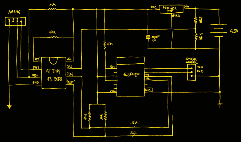
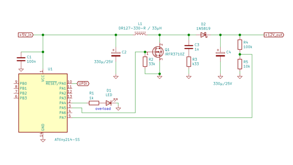
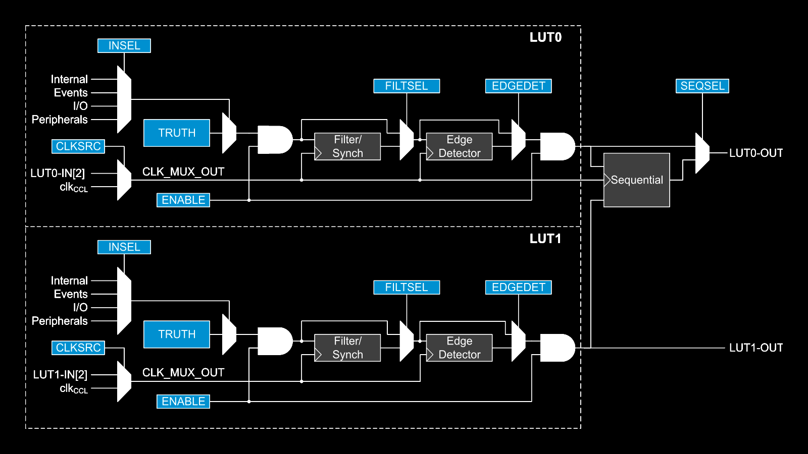
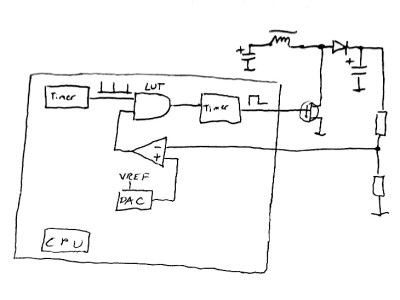
This napkinCAD sketch shows how [SM6VFZ] implemented the boost regulator in the ATtiny214. The AND gate is formed using one of the CCL LUT’s. The first “timer 1” on the left, connected to one input of the AND gate, is free running and set at 33 kHz. The analog comparator compares the boosted output voltage against an internally generated reference voltage derived from the DAC. The output of the comparator then “gates” timer 1 signal to trigger the second “timer 2” — which is a mono-shot timer set to max out at 15 us. This makes sure there is enough time left for the inductor to completely release its energy before the next cycle starts. You can check out the code that [SM6VFZ] used to built this prototype, and his generous amounts of commenting makes it easy to figure out how it works.

Based on this design, the prototype that he built delivers 12 V at about 200 mA with an 85% efficiency, which compares pretty well against regular switching regulators. Keep in mind that this is more of a proof-of-concept (that actually works), and there is a lot of scope for improvement in terms of noise, efficiency and other parameters, so everyone’s comments are welcome.

In an earlier blog post, we looked at how ATmegas with Programmable Logic came about with this feature that is usually found in PIC micro-controllers, thanks to Microchip’s acquisition of Atmel a few years back. But we haven’t seen any practical example of the CCL peripheral in an Atmel chip up until now.

Replacement LED Light Build Uses A Few Tricks

Microscopes have become essential work bench tools for hackers, allowing them to work with tiny SMD parts for PCB assembly and inspection. Couple of years back, mad scientist [smellsofbikes] picked up a stereo microscope from eBay. But its odd-sized, 12 volt Edison-style screw base lamp, connected to a 17 volt AC supply, burned off after a while. He swapped the burnt lamp with the spare, which too blew up after some time. Dumb lamps. Maybe the original spec called for 24 volt lamps, which were unobtanium due to the odd Edison screw base, but those would throw out a pretty yellow-orange glow. Anyhow, for some time, he worked with a jury-rigged goose neck lamp, but frequently moving the microscope and the lamp was becoming a chore. When he got fed up enough about it, he decided to Build a Replacement LED Microscope Light.

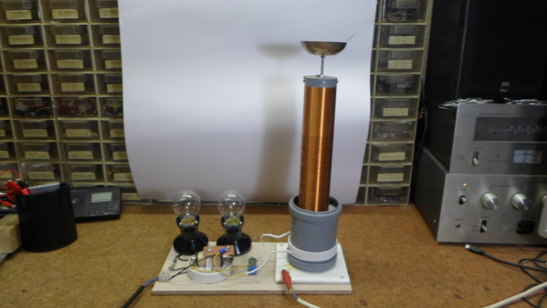
Usually, such builds are plain vanilla and not much to write in about, but [smellsofbikes] has a few tricks worth taking note of. He found a couple of high power, SMD LEDs in his parts bin. They were just slightly wider than 1.6 mm across the terminals. So he took a piece of double sided, copper clad FR4, and edge mounted the LED against one side of the PCB piece, twisting it slightly so he could solder both terminals. This works as a great heat sink for the LED while still having a very narrow profile. This was important as the replacement LED board had to fit the cylinder in which the original lamp was fitted.

The LED is driven by a constant current buck regulator, powered by the original 17 volt transformer. A bridge rectifier and several filter capacitors result in a low ripple DC supply, for which he used the KiCad spice functionality to work out the values. The LM3414 driver he used is a bit off the beaten track. It can run LEDs up to 60 watts at 1 amps and does not require an external current sense resistor. This was overkill since he planned to run the LED at just 150 mA, which would result in a very robust, long lasting solution. He designed the driver PCB in KiCad, and milled it on his LPKF circuit board plotter. The nice thing with CNC milled PCBs is that you can add custom copper floods and extend footprint pads. This trick lets you solder either a 0805 or a 1206 part to the same footprint – depending on what you can dig up from your parts bin.

Continue reading “Replacement LED Light Build Uses A Few Tricks”