The Thinkpad in question, with a Linux shell open on its screen, showing that the device mode has been successfully enabled

ThinkPad X1 Carbon Turned USB Device Through Relentless Digging

In what’s perhaps one of the most impressive laptop reverse engineering posts in recent memory, [Andrey Konovalov] brings us an incredibly detailed story of how he’s discovered and successfully enabled a USB device controller in a ThinkPad X1 Carbon equipped with a 6th gen Intel CPU.

If you ever wanted to peek at the dirty secrets of a somewhat modern-day Intel CPU-based system, this write-up spares you no detail, and spans dozens of abstraction layers — from Linux drivers and modifying NVRAM to custom USB cable building and BIOS chip flashing, digging deep into undocumented PCH registers for the dessert.

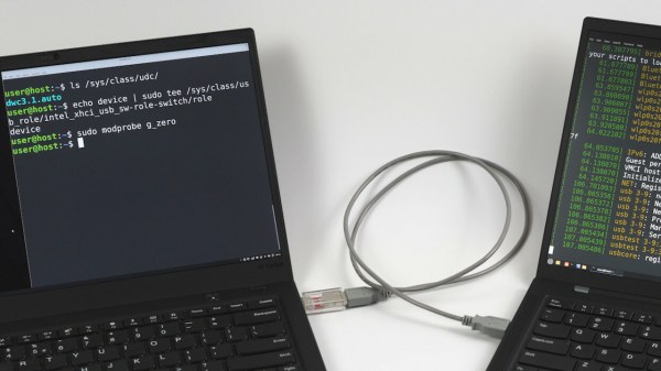
All [Andrey] wanted was to avoid tinkering with an extra Raspberry Pi. While using a PCIe connected device controller, he’s found a reference to intel_xhci_usb_sw-role-switch in Linux sysfs, and dove into a rabbit hole, where he discovered that the IP core used for the laptop’s USB ports has a ‘device’ mode that can be enabled. A dig through ACPI tables confirmed this, but also highlighted that the device is disabled in BIOS. What’s more, it turned out to be locked away behind a hidden menu. Experiments in unlocking that menu ensued, in particular when it comes to bypassing Intel Boot Guard, a mechanism that checks BIOS image signatures before boot.

Continue reading “ThinkPad X1 Carbon Turned USB Device Through Relentless Digging”

Pictures of the internals of the Starlink adapter

Restoring Starlink’s Missing Ethernet Ports

Internet connectivity in remote areas can be a challenge, but recently SpaceX’s Starlink has emerged as a viable solution for many spots on the globe — including the Ukrainian frontlines. Unfortunately, in 2021 Starlink released a new version of their hardware, cost-optimized to the point of losing some nice features such as the built-in Ethernet RJ45 (8P8C) port, and their proposed workaround has some fundamental problems to it. [Oleg Kutkov], known for fixing Starlink terminals in wartime conditions, has released three posts on investigating those problems and, in the end, bringing the RJ45 ports back.

Starlink now uses an SPX connector with a proprietary pinout that carries two Ethernet connections at once: one to the Dishy uplink, and another one for LAN, with only the Dishy uplink being used by default. If you want LAN Ethernet connectivity, they’d like you to buy an adapter that plugs in the middle of the Dishy-router connection. Not only is the adapter requirement a bother, especially in a country where shipping is impeded, the SPX connector is also seriously fragile and prone to a few disastrous failure modes, from moisture sensitivity to straight up bad factory soldering.

Continue reading “Restoring Starlink’s Missing Ethernet Ports”

Ethernet For Hackers: Equipment Exploration

Last time, we talked about the surface-level details of Ethernet. They are fundamental to know for Ethernet hacking, but they’re also easy to pick up from bits and pieces online, or just from wiring up a few computers in your home network. Now, there’s also a bunch of equipment and standards that you will want to use with Ethernet – easy to find whether used or new, and typically as easy to work with. Let’s give you a few beacons!

Routers And Switches

Whenever you see a box with a few Ethernet ports, it’s either referred to as a router, or a switch, sometimes people will even use the word “hub”! Fortunately, it’s simpler than it may seem. A router is a smart device, typically with an OS, that ties two or more networks together – routing packers from one network to another, and typically taking care of things like handing out local IP addresses via DHCP. A switch merely helps Ethernet devices exchange packets between each other on the same level – it’s typically nowhere near as smart as a router gets. Oftentimes, a home router will contain a switch inside, so that you can plug in multiple of your home devices at once. That’s the main difference – a switch merely transmits packets between Ethernet-connected devices, while a router is a small computer taking care of packet forwarding between networks and possibly including an Ethernet switch on the side.
Continue reading “Ethernet For Hackers: Equipment Exploration”

A breadboard showing a tiny ESP32 board and two HMC5883L sensors connected to it on different pins

Avoid I2C Address Conflicts On ESP32 By Pin Muxing

Using hardware I2C on an ESP32? Do you need to connect multiple I2C devices with the same address? Normally, you wouldn’t be able to do that without extra parts, but on the ESP32, [BastelBaus] has found a nice hack — just connect your devices to different pins and slightly abuse the ESP32 GPIO muxing, no extra hardware required!

Initially, they tried separating SDA and SCL completely, and after a bit of tinkering, that’s worked out wonders! For this method, [BastelBaus] provides example Arduino code you could easily integrate into your project, and shows logic analyzer captures that demonstrate there’s barely any overhead. Later, they’ve also found out that you could multiplex only one of the pins, specifically, SDA, having the SCL line be common! As far as we see, this could also work out with split SCL, but do let us know if that doesn’t sound right.

Typically, such a problem is solved with an I2C multiplexer, and we’ve highlighted projects with them before. However, this simple method could also work on chips like the RP2040 or even the Raspberry Pi 4 — just a bit more limited, since the GPIO muxing for I2C has less available ports! Also, if you’re not using a chip with such a comfortable GPIO mux and you must use devices with overlapping addresses, check out the comment section under our I2C ecosystem article – there’s a fair few other methods you can use. And, if this method ever malfunctions for you, there’s a bunch of very straightforward ways you could debug your bus!

An image showing the new KiCad feature that allows you to easily generate schematic labels from IC symbol pin names

KiCad 8 Makes Your Life Better Without Caveats

A few days ago, KiCad 8 was released, and it’s a straight upgrade to any PCB designer’s quality of life. There’s a blog post as usual, and, this year, there’s also a FOSDEM talk from [Wayne Stambaugh] talking about the changes that we now all get to benefit from. Having gone through both of these, our impression is that KiCad 8 developers went over the entire suite, asking: “this is cool, but could we make it better”? The end result is indeed a massive improvement in a thousand different ways, from small to fundamental, and all of them seem to be direct upgrades from the KiCad 7 experience.

Continue reading “KiCad 8 Makes Your Life Better Without Caveats”

Ethernet For Hackers: The Very Basics

Ethernet is ubiquitous, fast, and simple. You only need two diffpairs (four wires) to establish a 100Mbit link, the hardware is everywhere, you can do Ethernet over long distances easily, and tons of the microcontrollers and SoCs support it, too. Overall, it’s a technology you will be glad to know about, and there’s hundreds of scenarios where you could use it.

If you need to establish a high-bandwidth connection between two Linux boards in your project, or maybe a Linux board and a powerful MCU, maybe make a network between microcontrollers, Ethernet’s your friend. It also scales wonderfully – there’s so much tech around Ethernet, that finding cables, connectors or ICs tends to be dead easy. Plus, the world of Ethernet is huge beyond belief. Ethernet as most of us know it is actually just the consumer-facing versions of Ethernet, and there’s a quite a few fascinating industrial and automotive Ethernet standards that flip many of our Ethernet assumptions upside down.

Now, you might be missing out on some benefits of Ethernet, or perhaps misunderstanding how Ethernet works at all. What does it mean when a microcontroller datasheet says “has Ethernet interface”? If you see five pins on an SBC and the manufacturer refers to them as “Ethernet”, what do you even do with them? Why does the Raspberry Pi 4 SoC support Ethernet but still requires an extra chip, and what even is GMII? Continue reading “Ethernet For Hackers: The Very Basics”

Friendly Flexible Circuits: The Cables

Flexible cables and flex PCBs are wonderful. You could choose to carefully make a cable bundle out of ten wires and try to squish them to have a thin footprint – or you could put an FFC connector onto your board and save yourself a world of trouble. If you want to have a lot of components within a cramped non-flat area, you could carefully design a multitude of stuff FR4 boards and connect them together – or you could make an FPC.

Flexible cables in particular can be pretty wonderful for all sorts of moving parts. They transfer power and data to the scanner head in your flat-bed scanner, for instance.  But they’re in fixed parts too.  If you have a laptop or a widescreen TV, chances are, there’s an flexible cable connecting the motherboard with one or multiple daughterboards – or even a custom-made flexible PCB. Remember all the cool keypad and phones we used to have, the ones that would have the keyboard fold out or slide out, or even folding Nokia phones that had two screens and did cool things with those? All thanks to flexible circuits! Let’s learn a little more about what we’re working with here.

FFC and FPC, how are these two different? FFC (Flexible Flat Cable) is a pre-made cable. You’ve typically seen them as white plastic cables with blue pieces on both ends, they’re found in a large number of devices that you could disassemble, and many things use them, like the Raspberry Pi Camera. They are pretty simple to produce – all in all, they’re just flat straight conductors packaged nicely into a very thin cable, and that’s why you can buy them pre-made in tons of different pin pitches and sizes. If you need one board to interface with another board, putting an FFC connector on your board is a pretty good idea.

Continue reading “Friendly Flexible Circuits: The Cables”