The keyboard, fully assembled, with black 3D printed body.

From Product To Burnout To Open-Source: The Ergo S-1 Keyboard Story

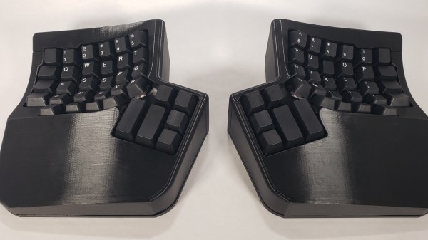
[Andrew] from [Wizard Keyboards] emailed us and asked if we were interested in his story of developing an ergonomic keyboard as a product. Many of us can relate to trying to bring one of our ideas to market. [Andrew], being a mechanical keyboard geek, knew a niche with no product to satisfy it, and had a vision he wanted to implement. He started meticulously going through steps for bringing his keyboard idea into life as a manufacturable product, and gave himself six months to get it done.

 Internals of the keyboard, showing the lower half with the mainboard on the left, and upper half of the keyboard with an FPC connecting keyswitches together on the right

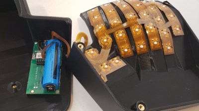
After evaluating competing products and setting a price point, he designed the case, the keyboard’s mainboard, and even flexible circuit boards for wiring the keys up. The mechanical design alone had him go through many iterations and decisions, and he walks us through the different paths he’s faced. Whether it’s these insights, a story of a module with fraudulent FCC certification, or an approach to electronics design that led to him passing EMC tests with flying colors, there’s plenty to learn from [Andrew]’s journey.

Sadly, at some point, the project quickly outgrew the intended goal and became a drain. For instance, tuning the 3D printing processes alone took three months instead of one as planned. As the design was done, he got stuck on marketing material production – a field that turned out to be unexpectedly hostile to a hacker like him. After a year of work and five thousand hours of work spent on the project, he took a break, and afterwards, as he was trying to come back, [Andrew] realized that he has burned out. He took a few month long hiatus, and having recovered a bit, revisited the project. Still not thrilled about the product route, he decided that open-sourcing the keyboard would be the best outcome – doing justice to the time and effort spent working on it.

This is where the story ends – for now. [Andrew] has open-sourced everything one would need to create such a keyboard by yourself, designed assembly instructions, and even sells kit parts for those who’d like to take a shortcut. This wasn’t what he aimed for, but it’s a honorable ending – most commercial projects never get open-sourced even if they utterly fail to launch. Thanks to [Andrew], we got an insightful journey, a postmortem, and an open-source ergonomic keyboard project. Product stories grace our pages every now and then – here’s a similarly swerving story about a MIDI controller.

Conference badge with the custom chip soldered-on on top left, the custom chip itself in a SOIC-16 package on the top right, two close-up die shots on the bottom

Student Competition Badge Bears Custom Silicon

[Daniel Valuch] shared a fun and record-setting conference badge story (Slovak, translated) with us. He was one of the organizers for the “ZENIT in electronics” event, which is an annual Slovak national competition for students. During the competition, students are assigned a letter+number code for the purpose of result submission anonymity, and organizers are always on the lookout for a fun way to assign these codes – this time, they did it with custom silicon!

It just so happened that [Peter], one of [Daniel]’s colleagues, was at the time working for onsemi who were doing a tapeout and had some free space on their test chips. Of course, they didn’t have to think twice. When it was a student’s turn to draw their identification number, instead of a slip of paper, they received a SOIC-16 package with custom silicon bonded to it. Then, they had to solder it to their competition badge – which was, of course, a PCB. Each chip was individually laser-trimmed to contain the student’s number, and that number could then be decoded using a multimeter – or a reasonably sharp eye.

There’s way more to this competition story than just the badge, but the custom silicon part of it sure caught our eyes. Who knows, maybe next year stars will align again and we’ll see custom silicon on one of the hacker conference badges. After all, things have been advancing rapidly on that front – for instance, since Skywater PDK project’s inception in 2020, there’s been several successful runs already, and if you’d like to learn more, you could check the HackChat we’ve had this year, and this Remoticon 2020 workshop!

The SDWire board plugged into some SoM's breakout board's MicroSD socket

Automated MicroSD Card Swapping Helps In Embedded Shenanigans

[Saulius Lukse] has been working on some single board computer, seemingly, running Linux. Naturally, that boots from a microSD card – and as development goes on, that card has to be reimaged all the time. Sick of constantly plugging and unplugging the microSD card between the SBC and an SD card reader, [Saulius] started looking for a more automated solution – and it wasn’t long before he found out about the SDWire project, a hardware tool that lets you swap a card between a DUT (Device Under Test) and your personal computer with no moving parts involved.

SDWire is an offshoot from the Tizen project, evidently, designed to be of help in device development, be it single-board computers or smartphones. The idea is simple – you plug your MicroSD card into the SDWire board, plug the SDWire into a MicroSD slot of your embedded device, and then connect a USB cable from the SDWire to your development computer. This way, if you need to reflash the firmware on the SBC you’re tinkering with, you only need to issue a command to the SDWire board over the USB cable, and the MicroSD card appears as a storage drive on your computer. SDWire is a fully open source project, both in hardware and in software, and you can also buy preassembled boards online.

Such shortening of development time helps in things like automated testing, but it also speeds your development up quite a bit, saving you time between iterations, freeing you from all the tiny SD card fiddling, and letting you have more fun as you hack. There’s a clear need for a project like SDWire, as we’ve already seen a hacker assemble such a device using breakouts.

Build A Tablet Out Of Your Framework Motherboard

The Framework laptop project is known for quite a few hacker-friendly aspects. For example, they encourage you to reuse its motherboard as a single-board computer – making it into a viable option for your own x86-powered projects. They have published a set of CAD files for that, and people have been working on their own Framework motherboard-based creations ever since; our hacker, [whatthefilament], has already built a few projects around these motherboards. Today, he’s showing us the high-effort design that is the FrameTablet – a 15″ device packing an i5 processor, all in a fully 3D printed chassis. The cool part is – thanks to his instructions, you can build one yourself!

This tablet sports a FullHD touchscreen IPS display and shows some well-thought-out component mounting, using heat-set inserts and screws, increasing such a build’s mechanical longevity. You lose one of the expansion card slots to the USB-C-connected display, but it’s a worthwhile tradeoff, and the touchscreen functionality works wonders in Windows. [whatthefilament] has also published a desk holder and a wall mount to accompany this design – if it’s a bit too large for you to hold in some situations, you can mount it in a more friendly, hands-free way. This is a solid and surprisingly practical tablet, and unlike the Raspberry Pi tablet builds we’ve seen, its x86 heart packs enough power to let you do things like CAD on the go.

With STLs and STEPs available, his build is a decent option for when you’ll want to replace your Framework’s motherboard with a new, upgraded one. You might’ve already noticed a few high-effort projects with these motherboards on our pages – perhaps, this transparent shell handheld with a mech keyboard and trackball, or this personal terminal with a futuristic-looking round display. This project is part of the “send 100 motherboards to hackers” initiative that Framework organized a few months ago, and we can’t say it hasn’t been working out for them!

Photo of the MCH2022 badge's screen, showing the "Hack me if you can" app's start splashscreen, saying "Service is accessible on IP ADDRESS : 1337"

MCH2022 Badge CTF Solved, With Plenty To Learn From

Among all the things you could find at MCH2022, there were a few CTFs (Capture The Flag exercises) – in particular, every badge contained an application that you could  try and break into – only two teams have cracked this one! [dojoe] was part of one of them, and he has composed an extensive reverse-engineering story for us – complete with Ghidra disassembly of Xtensa code, remote code execution attempts, ROP gadget creation, and no detail left aside.

There was a catch: badges handed out to the participants didn’t contain the actual flag. You had to develop an exploit using your personal badge that only contained a placeholder flag, then go to the badge tent and apply your exploit over the network to one of the few badges with the real flag on them. The app in question turned out to be an echo server – sending back everything it received; notably, certain messages made it crash. One man’s crashes are another man’s exploit possibilities, and after a few hacking sessions, [dojoe]’s team got their well-deserved place on the scoreboard.

If you always thought that firmware reverse-engineering sounds cool, and you also happen to own a MCH2022 badge, you should try and follow the intricately documented steps of [dojoe]’s writeup. Even for people with little low-level programming experience, repeating this hack is realistic thanks to his extensive explanations, and you will leave with way more reverse-engineering experience than you had before.

The MCH2022 badge is a featureful creation of intricate engineering, with the ESP32 portion only being part of the badge – we’re eager to hear about what you’ve accomplished or are about to accomplish given everything it has to offer!

A family of PixMob bracelets being coltrolled by an ESP32 with an IR transmitter attached to it. All the bracelets are shining a blue-ish color

PixMob Wristband Protocol Reverse-Engineering Groundwork

The idea behind the PixMob wristband is simple — at a concert, organizers hand these out to the concertgoers, and during the show, infrared projectors are used to transmit commands so they all light up in sync. Sometimes, attendees would be allowed to take these bracelets home after the event, and a few hackers have taken a shot at reusing them.

The protocol is proprietary, however, and we haven’t yet seen anyone reuse these wristbands without tearing them apart or reflashing the microcontroller. [Dani Weidman] tells us, how with [Zach Resmer], they have laid the groundwork for reverse-engineering the protocol of these wristbands.

Our pair of hackers started by obtaining a number of recordings from a helpful stranger online, and went onto replaying these IR recordings to their wristbands. Most of them caused no reaction – presumably, being configuration packets, but three of them caused the wristbands to flash in different colors. They translated these recordings into binary packets, and Dani went through different possible combinations, tweaking bits here and there, transmitting the packets and seeing which ones got accepted as valid. In the end, they had about 100 valid packets, and even figured out some protocol peculiarities like color animation bytes and motion sensitivity mode enable packets.

The GitHub repository provides some decent documentation and even a video, example code you can run on an Arduino with an IR transmitter, and even some packets you can send out with a  Flipper Zero. If you’re interested in learning more about the internals of this device, check out the teardown we featured back in 2019.

Here’s How The Precursor Protects Your Privacy

At some point, you will find yourself asking – is my device actually running the code I expect it to? [bunnie] aka [Andrew Huang] is passionate about making devices you can fundamentally, deeply trust, and his latest passion project is the Precursor communicator.

At the heart of it is an FPGA, and Precursor’s CPU is created out of the gates of that FPGA. This and a myriad of other design decisions make the Precursor fundamentally hard to backdoor, and you don’t have to take [bunnie]’s word for it — he’s made an entire video going through the architecture, boot protections and guarantees of the Precursor, teaching us what goes into a secure device that’s also practical to use.

Screenshot from the video, showing a diagram of how precursor's software and hardware components relate to each other If you can’t understand how your device works, your trust in it might be misplaced. In the hour long video, [bunnie] explains the entire stack, from the lower levels of hardware to root keys used to sign and verify the integrity of your OS, along the way demonstrating how you can verify that things haven’t gone wrong.

He makes sure to point out aspects you’d want to be cautious of, from physical security limitations to toolchain nuances. If you’re not up for a video, you can always check out the Precursor wiki, which has a treasure trove of information on the device’s security model.

As you might’ve already learned, it’s not enough for hardware to be open-source in order to be trustworthy. While open-source silicon designs are undoubtedly the future, their security guarantees only go so far.

Whether it’s esoteric hard drive firmware backdoors, weekend projects turning your WiFi card into a keylogger, or rootkits you can get on store-bought Lenovo laptops, hell, even our latest This Week In Security installment has two fun malware examples – there’s never a shortage of parties interested in collecting as much data as possible.