Hackaday Links: July 3, 2016

This week, Popular Mechanics published cutaway diagrams of ships that will be seen in Star Trek: Beyond, released later this month. This is your cue for spoilers for the remainder of this paragraph. The USS Franklin looks suspiciously like – and was likely built after – the NX-01, the titular ship of Star Trek: Enterprise. The Abrams-verse Franklin was the first Warp 4 ship, yet the prime universe NX-01 was the first Warp 5 ship, with previous ships having trouble reaching Warp 2. We must now consider the Abrams-verse Trek is not a parallel universe to prime-universe Trek and should therefore be considered a completely separate canon (yes, even the destruction of Vulcan. If you see the new Star Trek movie, the NX-01 launched in 2151, and your suggested viewing beforehand is ST:ENT, S02E24, First Flight.

The Mechaduino is a Hackaday Prize entry that turns steppers into closed-loop servos. It’s a phenomenal idea, and now it’s a Kickstarter.

Walk into a dollar store, and you’ll find stupid solar powered electronic flower pots. They’re bits of plastic that shake a plastic flower back and forth when placed in the sun. They’re selling millions, and I have no idea why. [Scott] put a jolly wrencher on one of these flower pots. Really, this is just an exercise in 3D printing, but [Scott] printed the jolly wrencher. We don’t see a lot of that, due to how difficult it is to render the wrencher in OpenSCAD.

In just a few hours, Juno will perform an insertion burn around Jupiter. Does this mean pretty pictures? Not quite yet. This is the closest a spacecraft has ever gotten to Jupiter, and over thirty or forty orbits, Juno will fly between Jupiter’s massive radiation belts. Here’s the NASA trailer.

This video recently caught the Internet’s attention. It’s squares and circles that when put next to a mirror look like circles and squares. Yes, it’s weird. People have 3D printers, so of course these ambiguous objects were quickly reverse engineered and printed. Here’s how they work

It looks like Brexit has caught up to Mouser. Here’s their country select dialog for eu.mouser.com. Thanks [Tom] for the screencap.
Bringing A Teletype Into The 21st Century

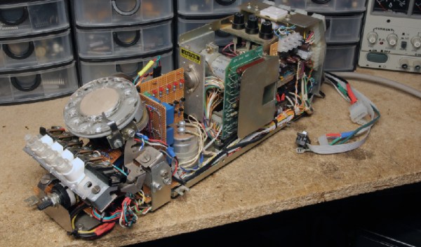
Before modern CRTs with ancient VGA connectors, and before fancy video terminals, the display for computers large and slightly smaller was the Teletype. While many of these Teletypes were connected directly, they were designed to be a remote terminal, connected through Ma Bell’s network. [NeXT] over on the Vintage Computer Forums is bringing the iconic ASR33 Teletype into the 21st century by giving this old display a modern way to connect to the outside world.

If you ever see a Teletype in action, it will be connected to a local machine. This was certainly not always the case. The Teletype was designed to connect to remote systems. [NeXT]’s Teletype came with a Call Control Unit designed for Telex lines, which do not exist anymore. Modems for the ASR33 existed, but good luck finding one. Lucky for [NeXT], nearly every modem ever made is backwards-compatible with the Bell Dataphone, one of the standard ways of plugging a Teletype into a phone line. All [NeXT] had to do was put a modem inside this Teletype.

With relays, transistors, LEDs, and a lot of perfboard, [NeXT] successfully built a circuit that would interface the Teletype’s Call Control Unit to a Hayes Smartmodem tucked away inside the stand. Believe it or not, this is an exceptionally useful build; if you ever find a Teletype tucked away in the back of an old office, in a surplus shop, or on Craigslist, odds are it won’t be compatible with any modern electronics. That’s not to say land lines are particularly modern, but since there’s a microcontroller included in the new circuitry, it’s relatively easy to add a USB port to this ancient terminal.

The Dual-Core, ARM-Powered Commodore 64

There is no CPU that is better understood than the 6502 and its cousins the 6510, 6507, 6509, and whatever we’re calling the CPU in the NES. With this vast amount of documentation, just about anything can be done. Want a discrete and un-discreet 6502? Sure thing. It’s the NMOS version, though. Want an emulated version. Sure. With libraries porting the 6502 to every platform ever, there’s only one place left to go: putting a 6502 in a Commodore 64. Make it dual-core, too, so we can run CP/M.

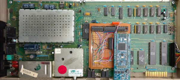
This build is based on one of [telmomoya]’s earlier builds – a soft-core 6510 running on an ARM Cortex M3. The inspiration for this build came from a 6502 emulator running on an Arduino, which got [telmomoya] wondering what would happen if he attached some external RAM, CIA or a SID. Doing this on an Arduino is hard, but there are a few 5 Volt tolerant ARM chips out there, and with a few banks of SRAM, [tel] quickly had an emulated 6502 running EhBasic.

Running an emulated 6502 on an ARM chip is nothing new. What makes this build spectacular is the adaptation to the C64 motherboard. Since [telmomoya] was already breaking out the data and address lines to go to the SRAMs, it didn’t take much extra work to simply build an adapter for the DIP40 CPU socket on a C64. A few 74-series logic chips made the interface easy, and after a bit of soldering, [telmomoya] had a Commodore 64 powered by an ARM chip.

If you’re emulating one chip, you can emulate two, and with the Commodore 64, this leads to a few interesting possibilities. The C64 had a CP/M cartridge — a cartridge that contained a Z80 CPU, sharing the data and address bus with the 6510. This cartridge allowed the ‘toy computer’ C64 to run the ‘business’ CP/M operating system (and the Z80 made the Commodore 128 much cooler).  Since [telmomoya] was already emulating a CPU, emulating a second CPU wasn’t really that hard.

It’s a phenomenal build, and great if you’ve ever wanted to speed up VisiCalc.

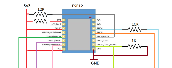
Wired Networking For The ESP8266

The ever popular ESP8266 is popping up in more and more projects. There are CNC controllers, blinkey WiFi lighting, and downright bizarre WiFi to Ethernet bridges. [Cicero] has thrown his hat into the ring with one of these Ethernet-enabled ESP8266 builds, and right now everything works, it’s simple to put together, and cheap to build.

Astute readers will notice we’ve seen something like this before. A few months ago, [cnlohr] discovered the Ethernet controller in the ESP8266. This was, by every account, the hard way of doing things. [cnlohr] was driving the Ethernet directly through the ESP’s I2S bus. [Cicero]’s project does not. It uses the cheap ENC28J60 SPI to Ethernet adapter to put the ESP on a wired network. Is one solution better than the other? That’s arguable. Is one solution much simpler than the other? Yes, [Cicero]’s work allows anyone to add Ethernet to the ESP8266 with a few resistors and a module that costs $3 from the usual online shops.

With the Ethernet stack taken from [Ulrich Radig], the SPI driver from [MetalPhreak], and an ESP8266-based web server from [Sprite_tm], [Cicero] managed to serve up web pages through both the wired and wireless connections.

Although this build is not as technically amazeballs as [cnlohr]’s work with driving Ethernet directly from the ESP, it is very easy to implement, opening up the doors to a few of the more interesting capabilities of a wired ESP. With the Ethernet unlocked, there’s a free WiFi interface to wardrive, snoop around in promiscuous mode, inject packets, bridge a bunch of ESPs in mesh mode to another network, and other network shenanigans. The ENC28J60 modules have probably already found their way into a few parts bins and junk boxes already, making [Cicero]’s work the quick start guide to wired networking on the ESP.

Thanks [PuceBaboon] for sending this one in.

1024 “Pixel” Sound Camera Treats Eyes To Real-Time Audio

A few years ago, [Artem] learned about ways to focus sound in an issue of Popular Mechanics. If sound can be focused, he reasoned, it could be focused onto a plane of microphones. Get enough microphones, and you have a ‘sound camera’, with each microphone a single pixel.

Movies and TV shows about comic books are now the height of culture, so a device using an array of microphones to produce an image isn’t an interesting demonstration of FFT, signal processing, and high-speed electronic design. It’s a Daredevil camera, and it’s one of the greatest builds we’ve ever seen.

[Artem]’s build log isn’t a step-by-step process on how to make a sound camera. Instead, he went through the entire process of building this array of microphones, and like all amazing builds the first step never works. The first prototype was based on a flatbed scanner camera, simply a flatbed scanner in a lightproof box with a pinhole. The idea was, by scanning a microphone back and forth, using the pinhole as a ‘lens’, [Artem] could detect where a sound was coming from. He pulled out his scanner, a signal generator, and ran the experiment. It didn’t work. The box was not soundproof, the inner chamber should have been anechoic, and even if it worked, this camera would only be able to produce an image or two a minute.

back
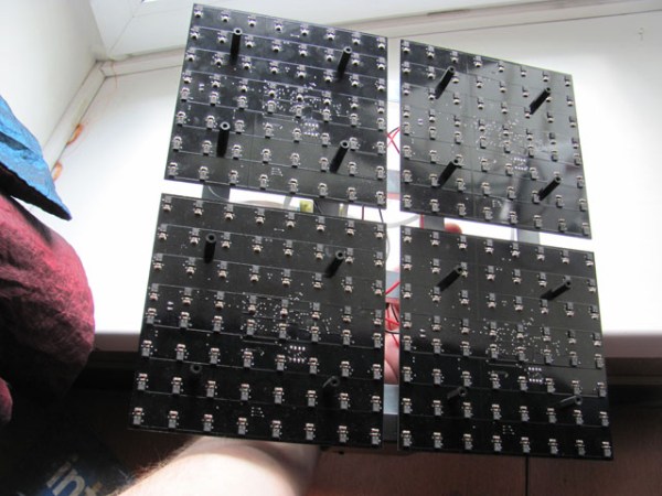
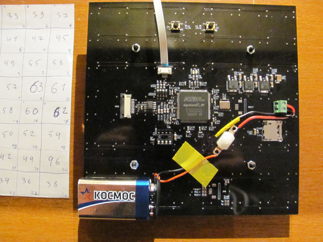
8×8 microphone array (mics on opposite side) connected to Altera FPGA at the center

The idea sat in the shelf of [Artem]’s mind for a while, and along the way he learned about FFT and how the gigantic Duga over the horizon radar actually worked. Math was the answer, and by using FFT to transform a microphones signals from up-and-down to buckets of frequency and intensity, he could build this camera.

That was the theory, anyway. Practicality has a way of getting in the way, and to build this gigantic sound camera he would need dozens of microphones, dozens of amplifiers, and a controller with enough analog pins, DACs, and processing power to make sense of all of this.

This complexity collapsed when [Artem] realized there was an off-the-shelf part that was a perfect microphone camera pixel. MEMS microphones, like the kind found in smartphones, take analog sound and turn it into a digital signal. Feed this into a fast enough microcontroller, and you can perform FFT on the signal and repeat the same process on the next pixel. This was the answer, and the only thing left to do was to build a board with an array of microphones.

4x4[Artem]’s camera microphone is constructed out of several modules, each of them consisting of an 8×8 array of MEMS microphones, controlled via FPGA. These individual modules can be chained together, and the ‘big build’ is a 32×32 array. After a few problems with manufacturing, the board actually worked. He was recording 64 channels of audio from a single panel. Turning on the FFT visualization and pointing it at a speaker revealed that yes, he had indeed made a sound camera.

The result is a terribly crude movie with blobs of color, but that’s the reality of a camera that only has 32×32 resolution. Right now the sound camera works, the images are crude, and [Artem] has a few ideas of where to go next. A cheap PC is fast enough to record and process all the data, but now it’s an issue of bandwidth; 30 sounds per second is a total of 64 Mbps of data. That’s doable, but it would need another FPGA implementation.

Is this sonic vision? Yes, technically the board works. No, in that the project is stalled, and it’s expensive by any electronic hobbyist standards. Still, it’s one of the best to grace our front page.

[Thanks zakqwy for the tip!]

Hackaday Prize Entry: An MRI Machine

Magnetic resonance imaging devices are one of the most fantastically incredible machines humans have ever built. They’re capable of producing three-dimensional images of living tissue by flipping protons around with a magnetic field. Ninety percent of the population doesn’t know what that sentence means, yet you can find an MRI machine inside nearly any reasonably equipped hospital in America.

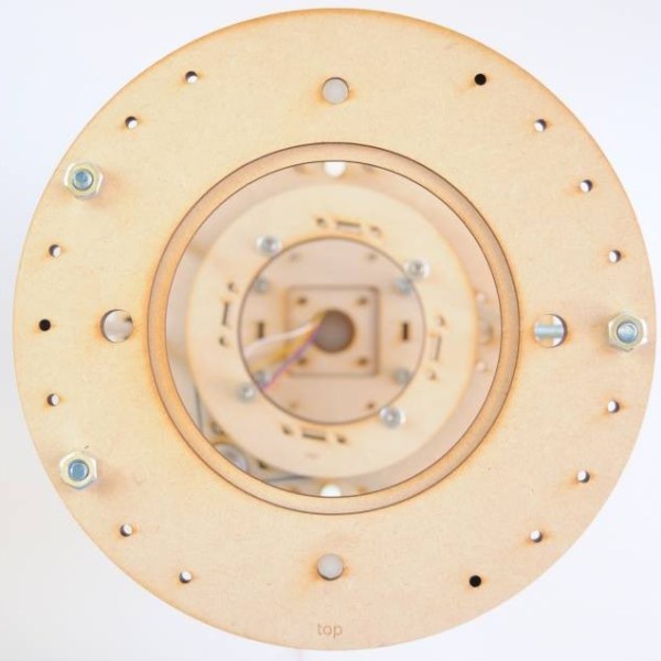
For his Hackaday Prize entry, [Peter Jansen] is building a magnetic resonance imager, capable of producing the same type of images you’d get from the radiology department at a hospital. It’s going to be a desktop unit, capable of scanning fruit and other similarly sized objects, and can be built using tools no more advanced than a hot air gun and a laser cutter.

This project is a continuation of what should have been [Peter]’s Hackaday Prize entry last year. Things got busy for him last summer, he dropped out of the Hackaday Prize, which means he’s welcome to continue his build this year.

Last year, [Peter] developed the plywood mechanism that would rotate a magnetic sensor across the diameter of the scanning volume, rotate the object to be scanned, and lift the object through the volume. It’s a weird 3-axis CNC machine, basically, but the parts near the magnetic sensor can’t be made out of metal. Dental floss worked okay, but we have a few hundred feet of Spectra fishing line if we ever bump into [Peter]. Magnetic resonance imaging means big coils of wire, too, which means the tedious task of winding coils around a cylinder is part of the build. [Peter] built a machine to do the work for him.

This is not [Peter]’s first attempt at building an imaging device. He built a desktop CT scanner that is exceptionally slow, but does shoot radiation through fruit to produce an image. His first project on Hackaday.io was the Open Source Science Tricorder, one of the top five finalists in the first year of the Hackaday Prize.

Already, [Peter] has some amazing work under his belt that produces real data that could not be otherwise obtained. An Open Source MRI is the perfect project for the Hackaday Prize’s Citizen Science phase, and we’re very happy to see him enter this project.

The HackadayPrize2016 is Sponsored by:

A Hydra Of A 3D Printer

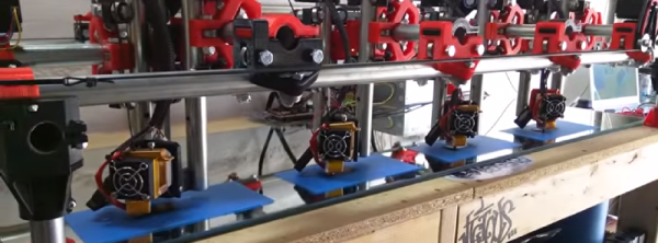
3D printers are great for producing one thing, but if you need multiple copies, the workflow quickly starts to go downhill. The solution? Build a 3D printer with multiple print heads, capable of printing four objects in the same amount of time it takes to print one.

This build is an experiment for [allted]’ Mostly Printed CNC / MultiTool. It’s a CNC machine that uses printed parts and 3/4″ electrical conduit for the frame and rails.  That last bit is the interesting part: electrical conduit is cheap, easy to acquire, available everywhere, and can be cut with a hacksaw. As far as desktop CNC machines go, it doesn’t get simpler or cheaper than this, and a few of these builds are milling wood with the same quality of a machine based on linear rails. It won the grand prize in the recent Boca Bearings contest, and is a great basis for a cheap and serviceable 2.5 or 3D CNC.

[allted] already has this cheap CNC mill cutting aluminum and engraving wood with a laser, showing off the capabilities of a remarkably cheap but highly expandable CNC machine. It’s a fantastic build, and we can’t wait to see more of these machines pop up in garages and workspaces.

Continue reading “A Hydra Of A 3D Printer”