Custom Powerbank In Compact Form Factor

The wide availability and power density of 18650 lithium-ion cells have made them a good option for everything from electric cars to flashlights. [Theo] needed a new power source for his FPV drone goggles, so he designed his own power bank with a very compact charge controller.The narrow PCB slips in between the cells
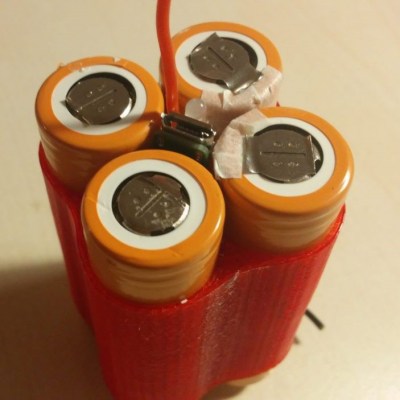
While [Theo] could charge the batteries with an RC battery charger, he preferred the convenience of one with a standard 5V micro USB input, and wanted battery level indication to avoid having the FPV goggles die unexpectedly mid-flight. When four 18650 cells are held in a cube arrangement, a 8x8x65 mm gap is formed between the cells. In this space [Theo] was able to fit a custom PCB with a micro USB jack, 1.3 mm power jack, BQ25606 charge controller, TPS61085 boost converter, and ATtiny MCU with LED for battery level feedback. The charge controller also allows 5V devices to be charged via USB, while the boost converter outputs 9V via the 1.3mm jack for [Theo]’s FPV goggles. Everything fits inside a nice compact 3D printed enclosure.

The project was not without hiccups. After ordering and building the PCB he discovered some minor PCB layout mistakes, and realized the boost converted could only output 600mA at 9V, which was not enough for his more power-hungry googles. He plans to fix this in the next version.

We’ve seen custom power banks in quite a few shapes and sizes, including one that runs on power tool batteries (which probably also have 18650s inside) and one that has just about every output you could want, including AC and wireless QI charging.

Ten Robot Mechanisms For Your Design Toolbox

The convergence of mechanics and electronics in robotics brings with it a lot of challenges. Thanks to 3D printing and low cost components, it’s possible to quickly and easily experiment with a variety of robotics mechanism for various use cases. [Paul Gould] has been doing exactly this, and is giving us a taste of ten designs he will be open sourcing in the near future. Video after the break.

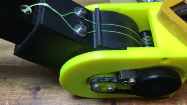
Three of the designs are capstan mechanisms, with different motors and layouts, tested for [Paul]’s latest quadruped robot. Capstan mechanisms are a few centuries old, and were originally used on sailing ships to give the required mechanical advantage to tension large sails and hoist cargo.

Two of the mechanisms employ GUS Simpson Drives, which use a combination of belts and a rolling joint. These were inspired by the LIMS2-AMBIDEX developed at the University of Korea. The ever-popular cycloidal gearbox also makes and appearance in the form of a high torque dual disk linked, two stage, NEMA17 driven gearbox.

[Paul] also built a room sized skycam-like claw robot for his daughter, suspended by four ball chain strings reeled in by four brushless motors with ESP32 powered motor controllers. We are looking forward to having a close look at these designs when [Paul] releases them, and to see how his quadruped robot will turn out.

[Thanks TTN for the tip!]

Tank Track Skateboard

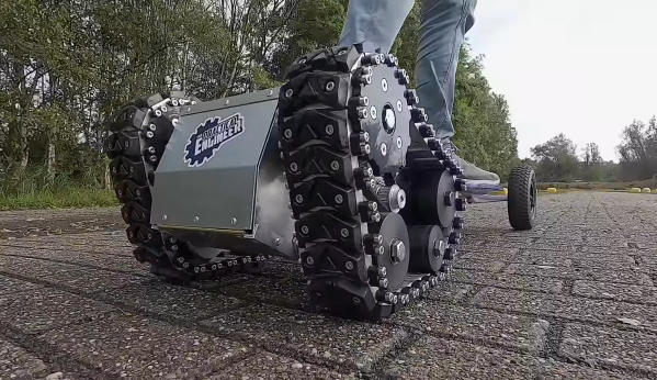
As electric skateboards kits and components become more commonly available, you really need to do something different to make your custom board stand out. [Emiel] [The Practical Engineer] has managed to do this by building a half-track skateboard. (Video, embedded below.)

Except for the front trucks, fasteners and bearings, all the mechanical components on the board were custom-made. The sturdy rear chassis and the track sections were machined from aluminum plate, and the wheels and track linkages were machined from POM/Delrin. The large carbon fiber deck and the polyurethane pads on the tracks were custom molded, which [Emiel] covered in detail in separate videos, also below. Two beefy brushless motors drive the tracks and are powered by LiPos in enclosed in the sheet metal electronics box. The final product looks very well-built and refined, especially considering most of the work happened in a tiny 2 m x 3 m workshop.

It looks like the board handles gravel paths well, but we would really like to see how it performs on soft surfaces like sand, where even off-road skateboards can struggle. It struggled a bit with low RPM torque, so a slight gearing change is in this board’s future.

Everything is cooler with tank tracks. If you’re willing to live with plastic tracks, 3D printing is a viable option, as demonstrated by [rctestflight]’s tracked rover and [Ivan Miranda]’s tank  skateboard. Continue reading “Tank Track Skateboard”

Hypercar Valve Technology On A Harbour Freight Engine

The inlet and exhaust valve timing of a piston engine plays a large role in engine performance. Many modern automotive engines have some sort of variable valve timing, but the valves are still mechanically coupled together and to the crankshaft. This means that there is always a degree of performance compromise for various operating conditions. [Wesley Kagan] took inspiration from Koenigsegg’s camless Freevalve technology, and converted a Harbour Freight engine to camless technology for individual valve control.

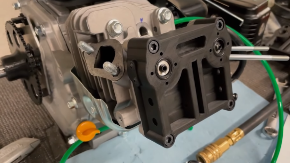
By eliminating the traditional camshaft and giving each valve its actuator, it is possible to tune valve timing for any specific operating condition or even for each cylinder. A cheap single-cylinder engine is a perfect testbed for the garage hacker. [Wesley] removed the rocker arms and pushrods, and replaced the stock rocker cover with a 3D printed rocker cover which contains two small pneumatic pistons that push against the spring-loaded valve stems. These pistons are controlled by high-speed pneumatic solenoid valves. A reference timing signal is still required from the crankshaft, so [Wesley] built a timing system with a 3D printed timing wheel containing a bunch of embedded magnets and being sensed by a stationary Hall effect sensor. An Arduino is used to read the timing wheel position and output the control signals to the solenoid valves. With a rough timing program he was able to get the engine running, although it wouldn’t accelerate.

In the second video after the break, he makes a digital copy of the engine’s existing camshaft. Using two potentiometers in a 3D printed bracket, he measured push rod motion for a complete engine cycle. He still plans to add position sensing for each of the valves, and after a bit more work on the single-cylinder motor he plans to convert a full-size car, which we are looking forward to.

People have been tinkering with cars in their garage for as long as cars have existed. [Lewin Day] has been doing a series on how to get into tinkering with cars yourself. With all the electronics in modern automobiles, messing around with their software has become a growing part of this age-old pastime. Continue reading “Hypercar Valve Technology On A Harbour Freight Engine”

Sit Up Straight!: Open Source Bluetooth Posture Sensing

As more and more people spend their working hours behind a computer, bad posture and the accompanying back pain and back problems become a growing epidemic. To combat this in his own daily life, [ImageryEel] made PosturePack, a wearable Bluetooth-enabled posture sensor.

The PosturePack is designed to fit into a small pocket sewn into the pack of an undershirt, between the shoulder blades. It consists of a custom PCB with an ATmega32U4, BNO055 IMU, Bluetooth module,  small LiPo and power circuitry. Based on the orientation data from the IMU, a notification is sent over Bluetooth to a smartphone whenever the user hunches forward.

[ImageryEel] says although the mobile notifications worked, haptic feedback integrated into the unit would be a better option. This could also be used to remind the user to stand up and take a break now and then, and provide an alternative to a smartwatch for activity monitoring without sending every movement to someone else’s servers. Software will always be the hardest part for projects like these, especially as the device become “smarter”. Learning to recognize activity and postures is actually a good place for tiny machine learning models.

Compared The posture sensors we covered before had to be installed and set up at a specific workstation, like an ultrasound-based version attached to a chair, and a webcam-based version.

Giving Blind Runners Independence With AI

Being able to see, move, and exercise independently is something most of us take for granted. [Thomas Panek] was an avid runner before losing his sight due to a genetic condition, and had to rely on other humans and guide dogs to run again. After challenging attendants at a Google hackathon, Project Guideline was established to give blind runners (or walkers) independence from a cane, dog or another human, while exercising outdoors. Using a smartphone with line following AI software, and bone conduction headphones, users can be guided along a path with a line painted on it. You need to watch the video below to get a taste of just how incredible it is for the users.

Getting a wheeled robot to follow a line is relatively simple, but a running human is by no means a stable sensor platform. At the previously mentioned hackathon, developers put together a rough proof of concept with a smartphone, using its camera to recognize a painted line on the ground and provide left/right audio cues.  As the project developed, the smartphone was attached to a waist belt and bone conduction headphones were used,  which don’t affect audio situational awareness as much as normal headphones.

The shaking and side to side movement of running, and varying light conditions and visual obstructions in the outdoors made the problem more difficult to solve, but within a year the developers had completed successful running tests with [Thomas] on a well-lit indoor track and an outdoor pedestrian path with a temporary line. For the first time in 25 years, [Thomas] was able to run independently.

While guide dogs have proven effective for both daily life and running, they cost approximately $60000 over an average working life of 8 years, putting them out of reach of many sight-impaired people around the world. Project Guideline is still in the early stages, and real-world problems like obstacles and traffic still need to be addressed, but there is massive potential.

Continue reading “Giving Blind Runners Independence With AI”

Microstepping A PCB Motor

Over the last 2 years [Carl Bujega] has made a name for himself with his PCB motor designs. His latest adventure is to turn it into a stepper motor by adding position control with microstepping.

The NEMA stepper motors most of us know are synchronous stepper motors, while [Carl]’s design is a permanent magnet design. It uses four coils on the stator, and two permanent magnets on the rotor/dial. By varying the current through each of the four poles with a stepper driver (microstepping), the position of the rotor should theoretically be controllable with good resolution. Unfortunately, this was easier said than done. He achieved position control, but it kept skipping steps in certain positions.

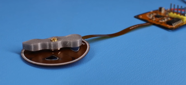
The motor and controller consist of a single flexible PCB, to reduce the layer spacing and increase the coils’ magnetic field strength. However, this created other problems, since the motor shaft didn’t have a solid mounting point, and the PCB flexed as the stator coils were energized. Soldering the controller was also a problem, as the through-hole headers ripped out easily and the PCB bulged while reflowing on a hot plate, in one case even popping off components. [Carl] eventually mounted one of the PCB motors inside a 3D printed frame to rigidly constrain all the motor components, but it still suffered from missed steps. Any suggestions for fixing the problem? Drop them in the comments below.

Like his other PCB motors, the torque is very low, but should be suitable for gauges or clocks. A PCB clock with an integrated motor would be pretty cool to have on the workshop wall.

The TMC2300 stepper driver [Carl] used belongs to the same family of drivers that enable silent stepping for 3D printers. We’ve covered a few of [Carl]’s PCB actuator adventures, from his original design to linear actuators and a flexible POV display.

Continue reading “Microstepping A PCB Motor”