JBC soldering station sitting atop a custom switch box next to a selection of hot ends.

A 3-tool Selector Box For A JBC Soldering Station

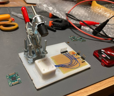
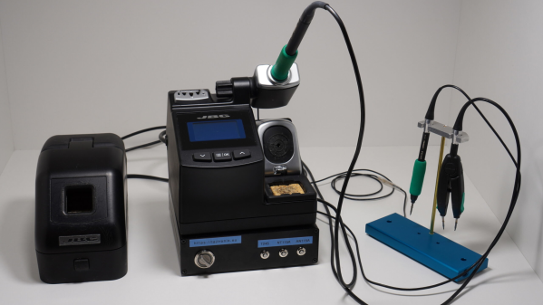
Soldering is one of those jobs that are conceptually simple enough, but there’s quite a bit of devil in the detail and having precisely the right tool for the job in hand is essential for speed and quality of results. The higher-quality soldering stations have many options for the hot end, but switching from a simple pencil to hot tweezers often means unplugging one and reattaching the other, and hoping the station recognises the change and does the right thing. [Lajt] had three soldering options and a single output station. Their solution was a custom-built three-way frontend box that provides a push-button selection of the tool to be connected to the station sitting atop.

[Lajt] shows in the blog post how each of their target hot ends is wired and the connectivity the control station expects to determine what is plugged in. Failing to recognise a connected 50 W heating element as if the smaller 25 W unit was still connected would suck, with a huge amount of lag as the temperature of the hot end would fail to keep up with the thermal load during use. When connections are made, it is important to ensure the unit has sufficient time to detect the change in output and configure itself appropriately. An Arduino Pro mini handles the selection between outputs by driving a selection of relays with appropriate timing. An interesting detail here is what [Lajt] calls a ‘sacrificial relay’ in the common ground path, which has a greater contact rating than the others and acts as a secondary switch to save wear on the other relay contacts that would otherwise be hot-switched. All in all, a nicely executed project, which should offer years of service.

We like DIY tools and tool-related hacks. Here’s a DIY Hakko station, a Weller clone unit, and a peek inside TS1C portable unit.

Continue reading “A 3-tool Selector Box For A JBC Soldering Station”

A pixellated image of pinokio

On-click Install local AI Applications Using Pinokio

Pinokio is billed as an autonomous virtual computer, which could mean anything really, but don’t click away just yet, because this is one heck of a project. AI enthusiast [cocktail peanut] (and other undisclosed contributors) has created a browser-style application which enables a virtual Unix-like environment to be embedded, regardless of the host architecture. A discover page loads up registered applications from GitHub, allowing a one-click install process, which is ‘simply’ a JSON file describing the dependencies and execution flow. The idea is rather than manually running commands and satisfying dependencies, it’s all wrapped up for you, enabling a one-click to download and install everything needed to run the application.

But what applications? we hear you ask, AI ones. Lots of them. The main driver seems to be to use the Pinokio hosting environment to enable easy deployment of AI applications, directly onto your machine. One click to install the app, then another one to download models, and whatever is needed, from the likes of HuggingFace and friends. A final click to launch the app, and a browser window opens, giving you a web UI to control the locally running AI backend. Continue reading “On-click Install local AI Applications Using Pinokio”

3D printed test jig to determine the yield point of a centrally loaded 3D printed beam.

One Object To Print, But So Many Settings!

When working with an FDM 3D printer your first prints are likely trinkets where strength is less relevant than surface quality. Later on when attempting more structural prints, the settings become very important, and quite frankly rather bewildering. A few attempts have been made over the years to determine in quantifiable terms, how these settings affect results and here is another such experiment, this time from Youtuber 3DPrinterAcademy looking specifically at the effect of wall count, infill density and the infill pattern upon the strength of a simple beam when subjected to a midpoint load.

A tray of 3D printing infill patterns available in mainstream slicers
Modern slicers can produce many infill patterns, but the effect on real world results are not obvious

When setting up a print, many people will stick to the same few profiles, with a little variety in wall count and infill density, but generally keep things consistent. This works well, up to a point, and that point is when you want to print something significantly different in size, structure or function. The slicer software is usually very helpful in explaining the effect of tweaking the numbers upon how the print is formed, but not too great at explaining the result of this in real life, since it can’t know your application. As far as the slicer is concerned your object is a shape that will be turned into slices, internal spaces, outlines and support structures. It doesn’t know whether you’re making a keyfob or a bearing holder, and cannot help you get the settings right for each application. Perhaps upcoming AI applications will be trained upon all these experimental results and be fed back into the slicing software, but for now, we’ll just have to go with experience and experiment. Continue reading “One Object To Print, But So Many Settings!”

apple airtag being opened to remove the sounder

Apple AirTag: Antitheft Or Antistalking?

Occasionally, the extra features added to a product can negate some of the reasons you wanted to buy the thing in the first place. Take, for example, Apple’s AirTag — billed as an affordable way to link your physical stuff to your phone. If some light-fingered ne’er-do-well wanders by and half-inches your gear, you get notified. The thing is, the AirTag also has an anti-stalking measure, which after a while, notifies nearby iPhones, should the tag move but not be near your iPhone!

In a recent video, [David Manning] explains that this feature is great for preventing the device from being used to track people. But it also means that if said thief happens to own an iPhone, they will be notified of the nearby tag, and can find it and disable it. So in the end, it’s a bit less useful as an anti-theft measure!

The solution is to pop the back off the tag and yank out the little sounder module from the rear plastic. You lose the ability to locate the tag audibly, but you gain a little more chance of returning your stolen goods. Apple could easily remove this feature with a firmware update, but it’s a matter of picking your poison: antistalking or antitheft?

Continue reading “Apple AirTag: Antitheft Or Antistalking?”

Need A Serial Data Plotter? Better Write Your Own

When you’re working with a development team, especially in a supporting capacity, you can often find yourself having to invent tools and support systems that are fairly involved, but don’t add to the system’s functionality. Still, without them, it’d be a dead duck. [Aidan Chandra] was clearly in a similar situation, working with a bunch of postgrads at Stanford, on an exoskeleton project, and needed an accurate data plotter to watch measurements in real-time.

This particular problem has been solved many times over, but [Aidan] laments that many solutions available seem to be too complex, hard to extend, or just have broken dependencies. This happens a lot, and it simply leads to yet another project to get going, before you can do the real work it supports. Based on Python and PyQT5, serial-plotter is a new beginning, with an emphasis on correct data acquisition and real-time data visualization with a little processing thrown in. Think, acquire data, show the raw values as well as the mean value, and RMS noise all on the same windows side-by-side, all of which is easily tweakable with a bit of programming using Numpy and Matplotlib.

One particularly important point to highlight is that of the handling of time-stamping. [Aidan] needed to ensure samples were logged together with a local MCU timestamp so that when displayed and possibly later post-processed, it was possible to accurately determine when a particular value or event occurred. With the amount of buffering, data loss and multiple-thread shenanigans, it is easy to forget that the data might get to the application in a non-deterministic way, and just relying on local CPU time is not so useful.

If you need to visualize data transported over the serial port, we have seen many projects to help. Like the highly configurable Serial Studio, for one. If your needs are a bit more complex, especially with multiple data transport methods, then a Supercon 2022 talk by [Alex Whittemore] might be a jolly good place to start.

A ZX Spectrum Raytracer, In BASIC

[Gabriel Gambetta] knows a few things about ray tracers, being the author of Tiny Raytracer, a raytracer written in just 912 bytes of JavaScript. As a long-time fellow sufferer of the UK-designed ZX Spectrum, could these two love affairs be merged? Could the Tiny Raytracer fit on the ZX Spectrum? In BASIC? The answer is an affirmative, albeit with our beloved speccy’s many limitations.

Ray tracing with only 15 primary colours

The story starts with [Gabriel]’s Computer Graphics From Scratch (CGFS) raytracer algorithms and an existing code base that was ported to the ZX Spectrum’s very limited BASIC dialect, using VSCode for editing, BAS2TAP to generate a tape image file (essentially an audio track) and executed with FUSE. With the toolchain sorted, [Gabriel] adds just enough code to deal with the ray intersection equations of a sphere, and renders a three-sphere scene to a 32×22 pixel colour image, taking a mere 15 minutes of runtime. Fellow sufferers will remember the spectrum had a 32×22 block attribute array (or colour array) with two colour values for foreground and background pixels. Each attribute block contains 8×8 pixels, each of which could be foreground (on) or background (off.) The next stage was then to expand the code to handle pixels as well as blocks, by simply expanding the raytracing to the full 256×176 resolution, and for each block simply determine the two most common colours, and run with those for the whole block. It sort of works, in a very spectrum-esq ‘attribute clash’ kind of fashion.

Continue reading “A ZX Spectrum Raytracer, In BASIC

A DIY E-Ink Tank Watch

[Augusto Marinucci] liked the classic Cartier Tank series of dress watches aesthetic, but wanted something a bit more techy, with a decent runtime on a single battery. E-Ink displays are often used in such applications, but finding one to fit a custom case design, is a tall order. When ordering one off the shelf is not easy, the solution is to make one from scratch.

Building a programming jig is a great idea for small-scale production

The article doesn’t have much information on the E-Ink side of things, which is a bit of a shame. But from what we can glean, the segment shapes — in this case, based on the famous Apollo DSKY — are formed in the top copper of a four-layer PCB, using filled and capped vias to connect invisibly from below.

A donor E-Ink display is cut to size with scissors (we don’t know much more than this!) and glued in place around the edge to make the common electrode connection. The display PCB attaches to the control PCB, at the rear using low-profile board-to-board connectors. This board hosts a PIC16 micro, as well as an RV-3028-C7 RTC which keeps time whilst consuming a paltry 45 nA.

Five volts are provided via a MAX1722 low-power boost converter which is fed power from the CR1616 cell via a couple of logic-controllable load switches. With a low-power design such as this, it’s critical to get this correct. Any mistakes here can easily result in a very low runtime. It is easy to over-stress small button cells and kill them prematurely.

The case looks like it’s printed in a translucent resin, with the PCB stack sealed inside with a UV-cured resin pour. It’s not immediately obvious if the rear panel can be removed to access the battery and programming port. There are what appear to be screw holes, so maybe that’s possible, or maybe they’re the rear side of the PCB mounting posts. Who can tell?

If DIY hardware is but too much effort for you, then there’s the option of hacking new firmware onto an existing watch, or perhaps meeting in the middle and making something out of all those junk E-ink tags you can get from time to time?

Thanks to [JohnU] for the tip!