SMA Connector Footprint Design For Open Source RF Projects

When you first start out in the PCB layout game and know just enough to be dangerous, you simply plop down a connector, run a trace or two, and call it a hack. As you learn more about the finer points of inconveniencing electrons, dipping toes into the waters of higher performance, little details like via size, count, ground plane cutouts, and all that jazz start to matter, and it’s very easy to get yourself in quite a pickle trying to decide what is needed to just exceed the specifications (or worse, how to make it ‘the best.’) Connector terminations are one of those things that get overlooked until the MHz become GHz. Luckily for us, [Rob Ruark] is on hand to give us a leg-up on how to get decent performance from edge-launch SMA connections for RF applications. These principles should also hold up for high-speed digital connections, so it’s not just an analog game.

Continue reading “SMA Connector Footprint Design For Open Source RF Projects”

Watch Out SiC, Diamond Power Semiconductors Are Coming For You!

The vast majority of semiconductors products we use every day are primarily constructed on a silicon process, using wafers of pure silicon. But whilst the economics are known, and processes mature, there are still some weaknesses. Especially for power applications. gallium nitride (GaN) and silicon carbide (SiC) are materials that have seen an explosion in uses in the power space, driven especially by an increase in electric vehicle sales and other high-power/high-voltage systems such as solar arrays. But, SiC is expensive and very energy intensive. It looks like diamond substrates could become much more common if the work by Diamfab takes off.

Diamond, specifically thin films of synthetic diamond formed on a suitable substrate, exhibits many desirable properties, such as a vastly superior maximum electric field compared with silicon, and a thermal conductivity five times better than copper. Such properties give diamond structures a big power and voltage advantage over SiC, which is in turn a lot better the pure silicon. This also means that diamond-based transistors are more energy efficient, making them smaller and cheaper, as well as better performing. Without the high formation temperatures needed for SiC, diamond could well be their downfall, especially once you factor in the reduced environmental impact. There is even some talk about solid-state, high-voltage diamond insulator capacitors becoming possible. It certainly is an interesting time to be alive!

We do cover news about future semiconductors from time to time, like this piece about cubic boron arsenide. We’ve also seen diamond being used as a battery, albeit a very weak radiative one.

[via EETimes]

Hackaday Prize 2023: Building A Relay ALU

There’s much truth in the advice that, to truly understand something, you need to build it yourself from the ground up. That’s the idea behind [Christian]’s entry for the Re-engineering Education category of the 2023 Hackaday Prize. Built as an educational demonstrator, this is a complete arithmetic-logic unit (ALU) using discrete relays — and not high-density types either — these are the big honking clear-cased kind.

The design is neatly, intentionally, partitioned along functional lines, with four custom PCB designs, each board operating on 4-bits. To handle a byte-length word, boards are simply cascaded, making a total of eight. The register, adder, logic function, and multiplex boards are the heart of the build with an additional two custom boards for visualization (using an Arduino for convenience) and IO forming the interface. After all, a basic CPU is just an ALU and some control around it, the magic is really in the ALU.

The fundamental logical operations operating upon two operands, {A, B} are A, ~A, B, ~B, A or B, A and B, A xor B, can be computed from just four relays per bit. The logic outputs do need to be fed into a 7-to-1 bit selector before being fed to the output register, but that’s the job of a separate board. The adder function is the most basic, simply a pair of half-adders and an OR-gate to handle the chaining of the carry inputs and generate the carry chain output.

3D printed cable runs are a nice touch and make for a slick wiring job to tie it all together.

For a more complete relay-based CPU, you could check out the MERCIA relay computer project, not to mention this wonderfully polished build.


More Ideas For Setting Up An Electronics Workbench

Setting up an electronics work area is a highly personal and situational affair, with many interesting problems to be solved, and for many of us, significant budget constraints. The requirements for electronics development vary wildly depending upon the sort of work to be undertaken, but there is core equipment that many of us would consider a bare minimum for usability. [Badar Jahangir Kayani] is at the start of his career as an electrical engineer, and has documented the kitting out of his personal work areas for others to learn from.

A place for everything, everything in its place

As we already touched upon, the cost is often the main driving factor determining what we end up with, and this cost-vs-performance/quality tradeoff is what makes some of us fret over a buying decision. Buying secondhand off eBay is an option, but a lack of warranty and the unknowable condition are not great selling points.

[Badar] has a good grasp of the basic concepts of usability, such as keeping the most frequently used tools, instruments, and components out in the open. Less frequently used stuff is stored in drawers, bins, and compartment boxes. Buying the same storage systems keeps things as consistent as much as possible since it makes storing them easier. We were particularly interested in the use of the cloud-based database solution, Airtable used to create a parts database for minimal outlay.

Oooh! Cable tray action

There is also a lot of detail about how to walk that cost/quality/performance tightrope and get the best-valued gear currently on the market. Some notable examples are the UNI-T UT61E Digital Multimeter for general test use, the Controleo3 reflow controller for SMT assembly, and the Omnifixo OF-M4 magnetic fixament kit for that fiddly wiring part. [Badar] also recommends the FumeClear Solder Fume Extractor, although they lament that particular bit of kit is still under evaluation.

Obviously, we’ve talked about work areas a lot on these pages, like this time. For those with more space, this flippin’ awesome bench will be of interest, and if space is tight (or travel is a regular thing) might we suggest this 3D printed DIN-rail mounting cube as a starting point?

A Bullet Time Video Booth You Can Build

[Sebastian Staacks] built a video booth for his wedding, and the setup was so popular with family, that it was only fitting to do one better and make some improvements to the setup, Matrix-style. The “bullet time” video effect was introduced by the classic movie franchise and makes for a splendid video transition effect for video montages.

Hardware-wise, the effect is pretty expensive, requiring many cameras at various angles to be simultaneously triggered, in order to capture the subject in a fixed pose with a rotating camera. Essentially you need as many cameras as frames in the sequence, so even at 24 frames per second (FPS), that’s a lot of hardware. [Sebastian] cheated a bit, and used a single front-facing camera for the bulk of the video recording, and twelve individual DSLRs covering approximately 90 degrees of rotation for the transition. More than that is likely impractical (not to mention rather expensive) for an automated setup used in as chaotic an environment as a wedding reception! So, the video effect is quite the same as in the movies, as this is a fixed pose, but it still looks pretty good.

A Pico-W hidden in there providing a BT connected interface button

[Sebastian] did consider going down the Raspberry Pi plus Pi-cam route, but once you add in a lens and the hassle of the casing and mounting hardware, not to mention availability and cost, snagging a pile of old DLSRs looks quite attractive. Connectivity to the camera is a simple 3.5 mm jack for the focus and trigger inputs, with frames read out via a USB connection.

For practical deployment, the camera batteries were replaced with battery eliminator adapters which step-up the 5 V from the USB connection to the 7.4 V the cameras need, but the current spike produced by the coordinated trigger of all twelve cameras overwhelmed any power supply available. The solution, to be practical, and not at all elegant, is to just have lots of power supplies hidden in a box. Sometimes you’ve just got a job to do.

Reproducing this at home might be a bit awkward unless you have exactly the same hardware to hand, but the principles are sound, and there are a few interesting details to dig into, if you were so inclined.

We’ve seen a few takes on the bullet-time effect over the years. We featured a Raspberry Pi-based hack, a couple of years back, and earlier still, someone even built a rig to take bullet-time videos of Tesla coil discharges, because why not?

Continue reading “A Bullet Time Video Booth You Can Build”

Op-Amp Challenge: Interactive Analog LED Wave Array

A while back, [Chris Lu] was studying how analog circuits, specifically op-amps can be used to perform mathematical operations and wondered if they could be persuaded to solve differential equations, such as the wave equation. After sitting on the idea for a few years, it was time to make it a reality, and the result is an entry into the Op-Amp Challenge.

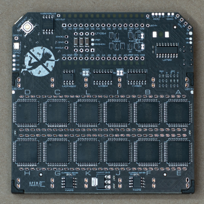
Unlike many similar interactive LED matrix displays that are digital in nature (because it’s a lot easier), this design is pure analog, using many, many op-amps. A custom PCB houses a 4×4 array of compute units, each with a blue and white LED indicating the sign and magnitude of the local signal.

The local input signal is provided by an IR photodiode, AC coupled to only respond to change, with every other circuit sharing a sensor to keep it simple. Each circuit is connected to its immediate neighbors on the PCB, and off the PCB via board-to-board connectors. This simple scheme makes this easily scalable if desired in the future.

[Chris] does a great job of breaking down the math involved, which makes this project a neat illustration of how op-amp circuits can implement complex mathematical problems in an easy-to-understand process. Even more op-amps are pressed into service for generating the split-rail voltage reference and for amplifying the weak photodiode signals, but the computation circuit is the star of the show.

We like analog computing a fair bit around these parts. Here’s a little something we were previously drooling over.

Continue reading “Op-Amp Challenge: Interactive Analog LED Wave Array”

A 4-Player Arcade Hidden Inside A Coffee Table

[Ed] from 50% Awesome on YouTube wanted to build a retro gaming system with a decent screen size, but doesn’t have a great deal of space to site it in, so a good compromise was to make a piece of useful furniture and hide all the fun parts inside.

Building an arcade machine usually involves a lot of wiring

This video two-part build log shows a lot of woodwork, with a lot of mistakes (happy accidents, that are totally fine) made along the way, so you do need to repeat them. Essentially it’s a simple maple-veneered plywood box, with a thick lid section hosting the display and some repositioned speakers. This display is taken from a standard LG TV with the control PCB ripped out. The power button/IR PCB was prised out of the bezel, to be relocated, as were the two downwards-facing speakers. The whole collection of parts was attached to a front panel, with copious hot glue, we just hope the heavy TV panel was firmly held in there by other means!

Continue reading “A 4-Player Arcade Hidden Inside A Coffee Table”