Homebrew HVAC systems are one of those projects that take such a big investment of time, effort and money that you’ve got to be a really dedicated (ideally home-owning) hacker with a wide variety of multidisciplinary skills to pull off an implementation that can work in reality. One such HVAC hacker is [Vadim Tkachenko] with his multi-zone Home Climate Control (HCC) project that we covered first back in 2007. We now have rare opportunity to look at the improvements fifteen years of part-time development can produce, when a project is used all day, all year round in their own home. At the start, things were simple, just opening and closing ventilators with none of those modern MQTT-driven cloud computing stuff. Continue reading “Is This The Oldest Open Source HVAC Project In Existence?”→
[Kasyan TV] over on YouTube was given a pile of spare parts in reasonably large quantities, some of which were useful and allocated to specific projects, but given the given the kind of electronics they’re interested in, they couldn’t find a use for a bag of 500 or so low specification 470uF capacitors. These were not low ESR types, nor high capacitance, so unsuitable for power supply use individually. But, what about stacking them all in parallel? (video, embedded below) After a few quick calculations [Kasyan] determined that the total capacitance of all 500 should be around 0.23 Farads with an ESR of around 0.4 to 0.5 mΩ at 16V and packing a theoretical energy total of about 30 joules. That is enough to pack a punch in the right situation.
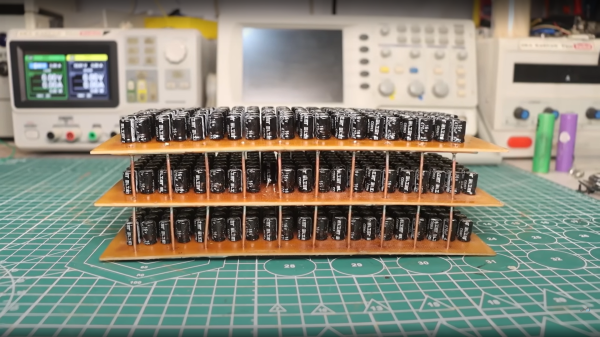
A PCB was constructed to wire 168 of the little cans in parallel, with hefty wide traces, reinforced with multiple strands of 1.8mm diameter copper wire and a big thick layer of solder over the top. Three such PCBs were wired in parallel with the same copper wire, in order to keep the total resistance as low as possible. Such a thing has a few practical uses, since the super low measured ESR of 0.6mΩ and large capacitance makes it ideal for smoothing power supplies in many applications, but could it be used to make a spot welder? Well, yes and no. When combined with one of the those cheap Chinese ‘spot welder’ controllers, it does indeed produce some welds on a LiPo cell with a thin nickel plated battery strip, but blows straight through it with little penetration. [Kasyan] found that the capacitor bank could be used in parallel with a decent LiPo cell giving a potentially ideal combination — a huge initial punch from the capacitors to blow through the strip and get the weld started and the LiPo following through with a lower (but still huge) current for a little longer to assist with the penetration into the battery terminal, finishing off the weld.
[Kaysan] goes into some measurements of the peak current delivery and the profile thereof, showing that even a pile of pretty mundane parts can, with a little care, be turned into something useful. How does such an assembly compare with a single supercapacitor? We talked about supercaps and LiPo batteries a little while ago, which was an interesting discussion, and in case you’re still interested, graphene-based hybrid supercapacitors are a thing too!
Many of the hardware orientated hackers among us will likely have been following along with the story of [Stephen Hawes] and the Lumen pick-and-place project but kind of waiting a bit for the project to mature some more before maybe taking the plunge and ordering a kit. One reason for this might be that whilst the basic machine design is there and working, the tape feeders did need a fair bit of work, and a lack of usable feeders does not make a great PnP machine. [Stephen] has been working on a newer design that addresses some of the identified shortcomings, and has started documenting his progress (video, embedded below) along the way.
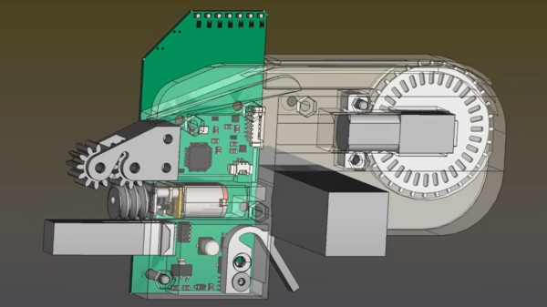
Gone is the PCB-based ‘case’, reverting back to a 3D printable affair and a much smaller PCB. After flip-flopping a bit between different geared DC motors, [Stephen] settled back on the original, smaller unit, which after a wee spot of hacking, was convinced to accept an optical encoder stripped from another unit, and this proved that it was indeed more than up to the tape-advancement duty. The reason for this change was physical size — the original motor resulted in an assembly 38mm wide — this limited the number for feeders on the front rail to barely eleven units. This is not really enough, but with the narrower assembly, the width is reduced to 15.5mm allowing 27 feeders to snuggle together on the rail, and that should make the machine much more usable.
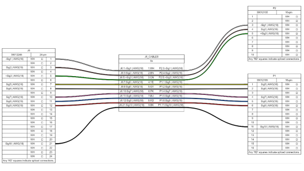
When building electronic assemblies there is quite often the need to construct custom cables to hook things up. It’s all very well if you’re prototyping by hand, or just building one or two of a thing, but if you’re cranking them out using outside help, then you’re going to want to ensure that cable is described very accurately. [Christian Nimako-Boateng Jr.] presents for us the first version of wirely, a wiring harness tool. This is a web-based tool that allows one to describe the cable ends and connectivity between them, producing a handy graphic and exports to excel in a format that should be easy to follow.
Based around the wireviz Python library running on a flask-based backend, image data are sent to the web assembly front-end and rendered with OpenGL. Configuration files can be imported and exported as JSON, making it easily linkable to other tools if required. Helpfully, the tool also seems to support some kind of revision control, although we didn’t try that yet. The process is straightforward enough, one simply defines a few groups (these relate to individual PCBs or other floating items in the assembly) which each contain one or more connectors. First, the connectors are described with part numbers, and wire gauge data, before defining the list of connections (wires) showing which signal and physical pins are connected together. Nothing more complex than that yet. We think there is still some more functionality that the tool could manage, such as shielding and guarding details, twisted pair definitions and a few others, but for a first pass, wirely looks pretty handy.
Visual cryptography is one of those unusual cases that kind of looks like a good idea, but it turns out is fraught with problems. The idea is straightforward enough — an image to encrypt is sampled and a series of sub-pixel patterns are produced which are distributed to multiple separate images. When individual images are printed to transparent film, and all films in the set are brought into alignment, an image appears out of the randomness. Without at least a minimum number of such images, the original image cannot be resolved. Well, sort of. [anfractuosity] wanted to play with the concept of visual cryptography in a slightly different medium, that of a set of metal plates, shaped as a set of keyrings.
Two image ‘share pairs’ needed as a minimum to form an image when combined
Metal blanks were laser cut, with the image being formed by transmitted light through coincident holes in both plate pairs, when correctly aligned. What, we hear you ask, is the problem with this cryptography technique? Well, one issue is that of faking messages. It is possible for a malicious third party, given either one of the keys in a pair, to construct a matching key composing an entirely different message, and then substitute this for the second key, duping both original parties. Obviously this would need both parties to be physically compromised, but neither would necessarily notice the substitution, if neither party knew the originally encrypted message. For those interested in digging in a little deeper, do checkout this classic paper by Naor and Shamir [pdf] of the Wiezmann Institute. Still, despite the issues, for a visual hack it’s still a pretty fun technique!
Want to learn a little more about crypto techniques you can do at home? Here’s our guide. Encryption too hard to break, but need a way to eavesdrop? Just punt out a flawed system, and you’re good to go.
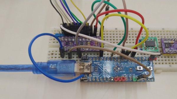
The iCE40 series of FPGAs gets a fair bit of coverage on these pages, largely due to its accessibility (thanks to huge efforts in reverse engineering and open tool chains) and likely also due to Lattice Semiconductors’ attitude to open source in general. Whilst these devices are small and rather limited, you can’t really beat them for a first foray into the subject. They’re plenty beefy enough for many of the simpler FPGA applications. [TinLethax] over on Hackaday.IO has plenty of experience with the devices, and has added another tool to our collective iCE40 arsenal, namely iCEBlaster, a USB mass storage device (MSC) style bootloader for drag-n-drop bitstream loading. The days of needing dedicated special programmers are starting to be numbered, with many chips now presenting a USB mass storage device to the host in order to upload the firmware image.
FPGAs don’t tend to operate this way, needing a device-specific bitstream loading upon start-up, which (unless they have OTP memory) is usually the job of an external configuration memory. iCEBlaster (a play on the Xilinx ByteBlaster programmer, maybe?) runs on the STM32F4xx series devices at least, but should be easily portable to others. The idea is pretty straightforward — dragging a new bitstream file onto the storage device initiates an FPGA target reset, which in turn allows the STM32 to send the bitstream over to the iCE40 via the SPI interface. Nothing more than that.
[shoobs] relocated from Australia to Luxembourg, and was really missing the whole outdoor cooking scene that is apparently very common in those parts. Now living in a modest apartment building in the city, he had no easy way to recreate some of his favorite cooking methods — specifically that of Wok Hei (breath of a wok) — the art of Cantonese stir-frying which uses searing heat and a lot of flinging around of the food to mix it up with the burning oil. This results in a complex set of reactions utilizing smoking, caramelization, and Maillard reactions to produce the classic Cantonese smoky flavor. Not wanting an off-the-shelf solution [shoobs] took it on himself to build a balcony cooking station capable of the temperatures needed for Wok Hei, and documented it for our viewing pleasure.
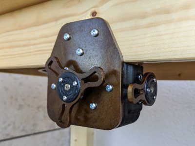
Nice custom laser cut details on the regulator mounting
The build started with sourcing a free-standing burner unit from Alibaba, which proved to be a little less powerful (at 30 kW) than ideal, but still sufficient. After locating a matching regulator and pressure gauge capable of the needed flow rate to feed the hungry burner, the next task was to construct a sturdy enough bench to mount it all. This was constructed from Douglas fir slabs, butt-jointed using a 3D printed drilling jig for ease of construction.
Using a flatbed scanner, the existing burner base was digitized in order to make a model suitable for laser-cutting a new mounting plate from steel. [Shoobs] isn’t lucky enough to have access to a metal-capable laser cutter — he sent his cad files off to a cutting service.
A second plate was mounted below with a sufficient gap above the bench to act as a heat shield. This keeps the wooden worktop safe from the heat. Whilst he was laser cutting steel, [shoobs] took the opportunity to design a few other custom parts to mount the regulator and other bits, because, why wouldn’t you? We reckon the end result is pretty nice, in a minimalist and understated way.
We’re no strangers to neat cooking hacks ’round these parts, here’s a nice double-sausage burner for those emergency situations and if you need a custom BBQ burner, then look no further.