The Eerie Sounds Of Ioalieia: An ESP32/Valve/Analog Hybrid Circuit Sculpture

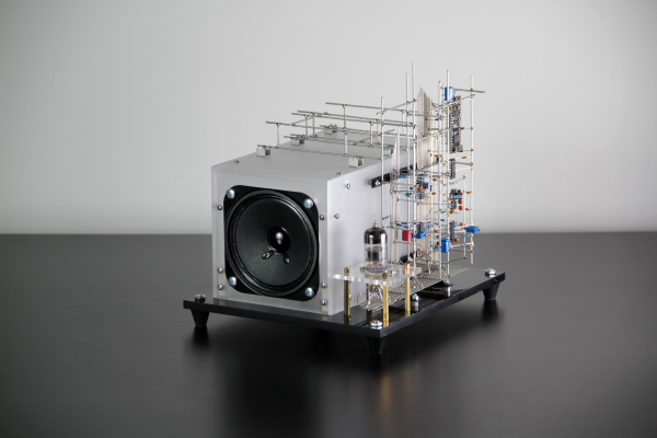
We’ve not had a circuit sculpture piece for a while, so here’s “ioalieia” a lovely hybrid digital-analog sound sculpture by [Eirik Brandal] to dig into.

Tidy straight lines. Nice job!

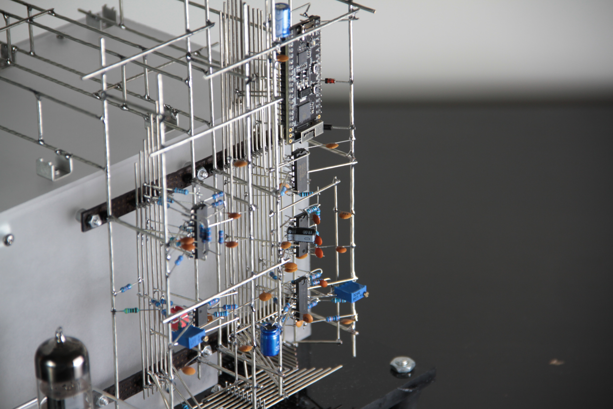
The host of the show is the ESP32 module, which generates audio frequency square waves, which are fed into a MCP4251 digital potentiometer. From there, it is fed into a AS3320 Voltage controlled filter (VCF), from Latvia-based ALFA (which is new to us, despite them being manufacturing electronics for sixty years!) This is an interesting device that has a four independently configurable filter elements with voltage controlled inputs for frequency control and resonance. The output from the VCF is then fed into a 6n2p (Soviet equivalent to the 12ax7) twin-triode vacuum tube, which is specifically aimed at audio applications.

The suitably distorted filtered square waves then pass into a Princeton Tech Corp PT2399 echo processor chip, which being digitally constructed, uses the expected ADC/RAM/DAC signal chain to implement an audio echo effect. As with the VCF, the echo depth can be modulated via the digipot, under the ESP32’s command. For a bit of added bling, the vacuum tube output feeds back into the ESP32, to be consumed by the internal ADC and turned into a light show via some PWM controlled LEDs. Lovely.

The final audio output from the echo chip is then fed into a speaker via a pair of LM380 amplifiers giving a power of about 5 W. It sounds pretty good if you ask us, and software configurable via Wi-Fi, giving this sculpture plenty of tweakabilty.

Of course circuit sculpture come in all shapes and sizes, and it wouldn’t do to not mention at least one sculpture clock project, and while we’re on it, here’s last year’s Remoticon circuit sculpture workshop.

Continue reading “The Eerie Sounds Of Ioalieia: An ESP32/Valve/Analog Hybrid Circuit Sculpture”

Rapid-Reload Vacuum Cannon Totally Demolishes Those Veggies

[NightHawkInLight] has been developing his design for a vacuum canon for a while now, so it seems fitting to drop in check out the progress. The idea is pretty straightforward, take a long rigid tube, insert a close fitting piston, magnetically attached to a projectile, and stopper the open end with something easily destroyed. The piston needs to be pulled into the tube with some force, to pull a vacuum against the stopper. The interesting bit happens next, when the piston exits the other end of the tube, with the vacuum at its maximum, there is a sudden inrush of air.  Apparently this inrush of supersonic velocity, and the momentum of the mass of air is sufficient to eject the projectile at considerable velocity, smashing through the plug and demolishing the target. So long as the target is of the soft and squishy variety anyway.

It’s an interesting idea, and certainly gives plenty of bang for not many bucks. That big lump of acrylic tubing (presumably used for ease of explanation in the video) looks fairly expensive to buy off the shelf, but we reckon any old pipe would probably work out fine.

We’ve definitely covered our share of DIY projectile weapons, like this air cannon made from PVC pipe parts, and of course there’s this crazy big one, that you should definitely not try at home.

Continue reading “Rapid-Reload Vacuum Cannon Totally Demolishes Those Veggies”

Soviet-Era Auto Dialler Uses Magnetic Rope Core Memory

We’ve seen a few interesting magnetic core memories on these fine pages over the years, but we don’t recall seeing too many user programmable magnetic core memory devices. This interesting Russian telephone auto dialer in its day would have been a very useful device, capable of storing and dialing forty user programmable 7-digit numbers. [mikeselectricstuff] tore into one (video, embedded below), and found some very interesting tech. For its era, this is high technology stuff. Older Russian tech has a reputation for incredibly ingenious use of older parts, that can’t be denied. After all, if it works, then there’s no need to change it. But anyway, what’s interesting here is how the designers decided to solve the problem of programming and recalling of numbers, without using a microprocessor, by using discrete logic and core rope memory.

This is the same technology used by the Apollo Guidance Computer, but in a user configurable form, and obviously much smaller storage capacity. The core array consists of seven, four-bit words, one word per telephone digit, which will be read out sequentially bottom to top. The way you program your number is to take your programming wire, insert it into the appropriate hole (one row related to numbers 1-20, the other row is shifted 1-20 for the second bank) and thread it along the cores in a weave type pattern. Along the way, the wire is passed through or bypasses a particular core, depending upon the digit you are coding for. They key for this encoding is written on the device’s lid. At the end, you then need to terminate the wire in the matching top connector, to allow the circuit to be completed.

As far as we can tell, the encoding is a binary sequence, with a special ‘stop’ code to indicate telephone numbers with less than seven digits. We shall leave further analysis to interested parties, and just point you at the Original manufacturer schematics. Enjoy!

Of course we’re not just going to mention rope core memory and the AGC without linking to a fantastic article about the very same, and if that’s wetting your appetite for making a rope core memory, here’s a little thing about that too!

Continue reading “Soviet-Era Auto Dialler Uses Magnetic Rope Core Memory”

A Simple EMF Detector And Electroscope You Can Make From Junk Box Parts

2N2222 devices used, but practically any junkbox NPN will do

Electromagnetic fields are everywhere, all around us. Some are generated naturally, but in vast majority of cases, it’s we humans that are generating them with artificial, electronic means. Everything from your mobile phone to the toaster will emit some sort of signal, be it intentional or not. So we think it only befits the general electronics-orientated hacker to have some way of sniffing around for these signals, so here is [Mirko Pavleski] with his take on a very simple pair of instruments to detect both static and dynamic electromagnetic fields.

CMOS clock input connected directly to the antenna. Warning! ESD damage risk!

The first unit (a simple electroscope) uses a cascade of 2N2222 NPN bipolar transistors configured to give a high current gain, so any charge near the antenna will result in increasing currents in subsequent stages, finally illuminating the LED. Simple stuff.

The second unit relies on the extremely high input impedance of the old-school CMOS 4017 decade counter, which is likely of the order of 100 MΩ or even more. Normally you would not leave such a CMOS input floating, or even connect it with too long a PCB trace — lest it pick up a stray signal —but for detecting alternating EM fields, this appears to work just fine. Configured as a simple divide-by-ten, when presenting 50 Hz AC, the LED can be seen to flash at 5 Hz.

Simple stuff, and this scribe has all those exact parts in the junk box, so will be constructing these shortly!

We’ve covered electroscopes for years, here’s a modern twist on a famous classic experiment, and some hair-raising experiments to get you started.

Continue reading “A Simple EMF Detector And Electroscope You Can Make From Junk Box Parts”

Low Cost Haptic VR Gloves Work With Hacked Steam Games

[Lucas VRTech] has made some significant progress with building force-feedback type haptic gloves for use with Steam VR games. The idea is pretty straightforward: the end of the finger is attached to a cable, which is pulled from inside a sprung-loaded spool; the kind used for hanging ID cards on.

The spool body can rotate, but a peg protruding from it engages with the arm of a co-located servo motor. This produces a programmable stop position. But it is a hard stop, and it is not possible with the current hardware to detect precisely when the stop is reached, nor is it possible to control the force it is pushing with. Such features are not difficult to achieve, its just a matter of a little more development with some custom mechatronics.

The current prototype has a focus on cost, which is great as an early development platform. By leveraging 3D printing and off-the-shelf parts that are easy to source; just a handful (chuckle!) of potentiometers, some servo motors and one from any number of ESP32 dev boards and you’re done. The real work is on the software side of things, as the games themselves need to be modified to play ball with the VR glove hardware. This has been achieved with a combination of a custom steam driver they call OpenGloves, and community developed per-game mods. A few titles are available to test right now, so this is definitely something some of us could build in a weekend and get involved with.

The hardware source for the glove mount and per-finger units can be found on the project GitHub, together with the ESP32 source for Arduino.

For some other haptic-related inspiration, here’s a force-feedback mouse, and for a more hand-off feedback, we have a wind-blaster project.

Continue reading “Low Cost Haptic VR Gloves Work With Hacked Steam Games”

Fail Of The Week: 3D Printed Parts That Burn Like NASA’s Rocket Fuel

[Integza] is on a mission to find as many ways as possible to build rockets and other engines using 3D printing and other accessible manufacturing techniques. He had an a great idea – is it possible to 3D print a solid fuelled rocket, (video, embedded below) specifically can you 3D print the rocket grain itself? By using the resin as a fuel and mixing in a potent oxidiser (ammonium perchlorate specifically – thanks for the tip NASA!) he has some, erm, mixed success.

Effective thrust vs grain cross-sectional profile

As many of us (ahem, I mean you) can attest to, when in the throes of amateur solid-propellant rocket engine experimentation (just speaking theoretically, you understand) it’s not an easy task to balance the thrust over time and keep the combustion pressure within bounds of the enclosure’s capability. Once you’ve cracked making and securing a nozzle within the combustion chamber, the easiest task is to get control of the fuel/oxidiser/binder (called the fuel grain) ratio, particle size and cast the mixture into a solid, dry mass inside. The hard part is designing and controlling the shape of the grain, such that as the surface of the grain burns, the actively burning surface area remains pretty constant over time. A simple cylindrical hole would obviously increase in diameter over time, increasing the burning surface area, and causing the burn rate and resulting pressure to constantly increase. This is bad news. Various internal profiles have been tested, but most common these days is a multi-pointed star shape, which when used with inhibitor compounds mixed in the grain, allows the thrust to be accurately controlled.

[Integza] tried a few experiments to determine the most appropriate fuel/binder/oxidiser ratio, then 3D printed a few fuel grain pellets, rammed them into an acrylic tube combustion chamber (obviously) and attached a 3D printed nozzle. You can see for yourself the mach diamonds in the exhaust plume (which is nice) due to the supersonic flow being marginally over-expanded. Ideally the nozzle wouldn’t be made from plastic, but it only needs to survive a couple of seconds, so that’s not really an issue here.

The question of whether 3D printed fuel grains are viable was posed on space stack exchange a few years ago, which was an interesting read.

We’ve seen some more sophisticated 3D printed rocket engines lately, such as this vortex-cooled, liquid-fuel engine, and over on Hackaday,IO, here’s a 3D printed engine attempting to use PLA as the fuel source.

Continue reading “Fail Of The Week: 3D Printed Parts That Burn Like NASA’s Rocket Fuel”

Advanced PCB Graphics With KiCAD 6 And Inkscape

There are many, many video tutorials about designing the functional side of PCBs, giving you tips on schematic construction, and layout tips. What is a little harder to find are tutorials on the graphical aspects, covering the process from creating artworks and how you can drive the tools to get them looking good on a PCB, leveraging the silkscreen, solder and copper layers to maximum effect. [Stuart Patterson] presents his guide for Advanced PCB Graphics in KiCAD 6.0 and Inkscape, (Video, embedded below) to help you on your way to that cool looking PCB build.

Silkscreen layers in yellow, solder mask opening in red

The first step is to get your bitmap, whether you create it yourself, or download it, and trace it into a set of vectors using the Inkscape ‘trace bitmap’ tool. If you started with an SVG or similar vector shape, then you can skip that stage.

Next simply create a PCB outline shape by deleting all the details that aren’t part of the outline. A little scaling here and there to get the dimensions correct and you’re done with the first part. [Stuart] has an earlier video showing that process.

The usability improvements in KiCAD 6.0 are many, but one greatly demanded feature is the ability to group objects, just like you do in Inkscape and any other vector graphics tool for that matter. That means you can simply import that SVG outline into the Edge.Cuts PCB layer and all the curves will be nicely tied together. Next you select the details you want for the silkscreen layer, solder mask removal layers and any non-circuit copper. In Inkscape it would be wise to use the layers feature to assign the different material types to a uniquely named layer, so they can be hidden for exporting. This allows you to handle silk, mask and copper PNG exports from a single master file, in addition to any vector details for outline, slots and holes.

Once you have PNG bitmap exports for the silk, mask etc. you need to create a footprint inside a board-specific library, using the KiCAD image converter tool. It was interesting to note that you can export a new image footprint from the tool and paste it straight into the footprint editor, and tweak all the visibility details at the same time. That will save some time and effort for sure. Anyway, we hope this little tutorial from [Stuart] helps, and we will be sure to bring you plenty more in the coming months.

Need some more help with KiCAD? Checkout this tutorial, and if you want a bit more power from the tool, you need some action plugins!

Continue reading “Advanced PCB Graphics With KiCAD 6 And Inkscape”