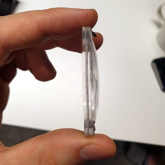
Valve’s unique multilayer lenses are far thinner than one might expect.
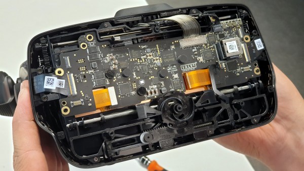
Want to see what exactly is inside the $500 (headset only price) Valve Index VR headset that was released last summer? Take a look at this teardown by [Ilja Zegars]. Not only does [Ilja] pull the device apart, but he identifies each IC and takes care to point out some of the more unique hardware aspects like the fancy diffuser on the displays, and the unique multilayered lenses (which are much thinner than one might expect.)
[Ilja] is no stranger to headset hardware design, and in addition to all the eye candy of high-res photographs, provides some insightful commentary to help make sense of them. The “tracking webs” pulled from the headset are an interesting bit, each is a long run of flexible PCB that connects four tracking sensors for each side of the head-mounted display back to the main PCB. These sensors are basically IR photodiodes, and detect the regular laser sweeps emitted by the base stations of Valve’s lighthouse tracking technology. [Ilja] also gives us a good look at the rod and spring mechanisms seen above that adjust distance between the two screens.
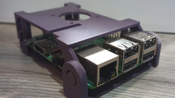
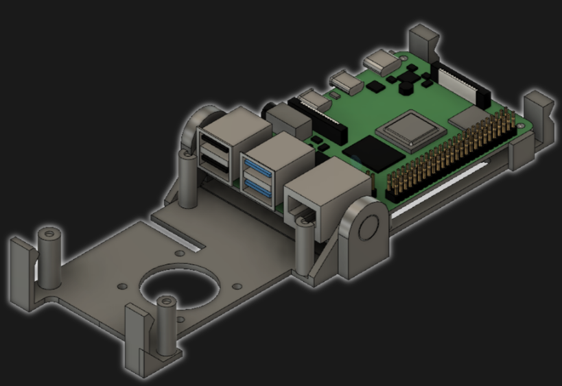
[jcprintnplay] has challenged himself to making Raspberry Pi cases in different ways, and his Fold-a-Pi enclosure tries for a “less is more” approach while also leveraging the strong points of 3D printing. The enclosure prints as a single piece in about 3 hours, and requires no additional hardware whatsoever.
The design requires no screws or other fasteners, and provides a mounting hole for a fan as well as some holes for mounting the enclosure itself to something. All the ports and headers are accessible, and the folding one-piece design is not just a gimmick; in a workshop situation where the Pi needs to be switched out or handled a lot, it takes no time at all to pop the Raspberry Pi in and out of the enclosure.
Microsoft’s 3D Builder has a pretty useful measurement tool for STLs.
[James] points out that the trick with a print-in-place hinge like this is leaving enough space between the parts so that the two pieces aren’t fused together, but not so much space that the print fails. He doesn’t go into detail about how much space worked or didn’t work, but an examination of the downloadable model shows that the clearance used looks like 0.30 mm, intended to be printed with a 0.4 mm nozzle.
[James] also demonstrates the value of being able to do quick iterations on a design when prototyping. In a video (embedded below) The first prototype had the hinge not quite right. In the second prototype there was a lack of clearance when closing. The third one solved both and shows the final design.
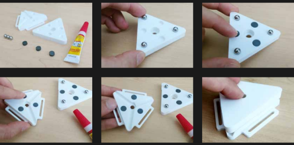
Time may bring change, but kinematic couplings don’t. This handy kinematic couplings resource by [nickw] was for a design contest a few years ago, but what’s great is that it includes ready-to-use models intended for 3D printing, complete with a bill of materials (and McMaster-Carr part numbers) for hardware. The short document is well written and illustrated with assembly diagrams and concise, practical theory. The accompanying 3D models are ready to be copied and pasted anywhere one might find them useful.
What are kinematic couplings? They are a way to ensure that two parts physically connect, detach, and re-connect in a precise and repeatable way. The download has ready-to-use designs for both a Kelvin and Maxwell system kinematic coupling, and a more advanced design for an optomechanical mount like one would find in a laser system.
The download from Pinshape requires a free account, but the models and document are licensed under CC – Attribution and ready to use in designs (so long as the attribution part of the license is satisfied, of course.) Embedded below is a short video demonstrating the coupling using the Maxwell system. The Kelvin system is similar.
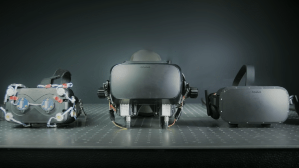
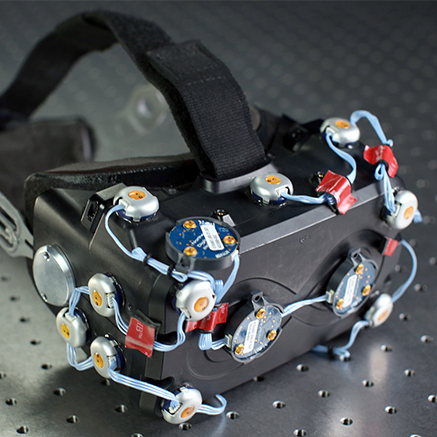
VR headsets are more and more common, but they aren’t perfect devices. That meant [Douglas Lanman] had a choice of problems to address when he joined Facebook Reality Labs several years ago. Right from the start, he perceived an issue no one seemed to be working on: the fact that the closer an object in VR is to one’s face, the less “real” it seems. There are several reasons for this, but the general way it presents is that the closer a virtual object is to the viewer, the more blurred and out of focus it appears to be. [Douglas] talks all about it and related issues in a great presentation from earlier this year (YouTube video) at the Electronic Imaging Symposium that sums up the state of the art for VR display technology while giving a peek at the kind of hard scientific work that goes into identifying and solving new problems.
Early varifocal prototype
[Douglas] chose to address seemingly-minor aspects of how the human eye and brain perceive objects and infer depth, and did so for two reasons: one was that no good solutions existed for it, and the other was that it was important because these cues play a large role in close-range VR interactions. Things within touching or throwing distance are a sweet spot for interactive VR content, and the state of the art wasn’t really delivering what human eyes and brain were expecting to see. This led to years of work on designing and testing varifocal and multi-focal displays which, among other things, were capable of presenting images in a variety of realistic focal planes instead of a single flat one. Not only that, but since the human eye expects things that are not in the correct focal plane to appear blurred (which is itself a depth cue), simulating that accurately was part of things, too.
The entire talk is packed full of interesting details and prototypes. If you have any interest in VR imaging and headset design and have a spare hour, watch it in the video embedded below.
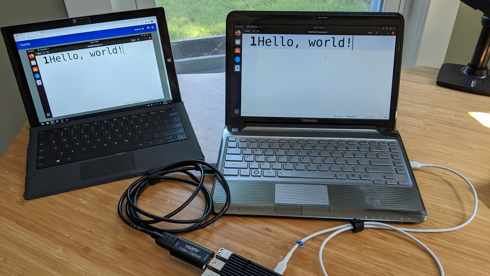
Remote access is great, but if the machine stops booting, ceases to connect to the network, or needs low-level interaction like BIOS settings or boot management, remote access is worthless because it’s only available once the host computer is up and running. The usual solution is to drag a keyboard and monitor to the machine in question for physical access.
Ubuntu laptop (right) being accessed over IP, via web browser on the left.
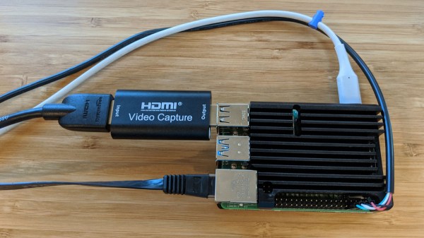
For most people, swapping cables in this way is an infrequent task at best. But for those who work more closely with managing hardware or developing software, the need to plug and unplug a keyboard and monitor into machines that otherwise run headless can get tiresome. The modern solution is KVM (keyboard, video, mouse) over IP, but commercial options are expensive. [Michael Lynch]’s TinyPilot on the other hand clocks in at roughly $100 of parts, including a Raspberry Pi and USB HDMI capture device. It does have to drop the ‘M’ from KVM (meaning it does not support a mouse yet) but the rest of it hits all the bases, and does it all from a web browser.
What exactly does TinyPilot do? It provides remote access via web browser, but the device is an independent piece of hardware that — from the host computer’s point of view — is no different from a physical keyboard and monitor. That means keyboard and video access works before the host machine even boots, so even changing something like BIOS settings is no problem.
[Michael] demonstrates his design in the video embedded below, but we encourage you to check out the project page for a fascinating exploration of all the challenges that were part of TinyPilot’s development.
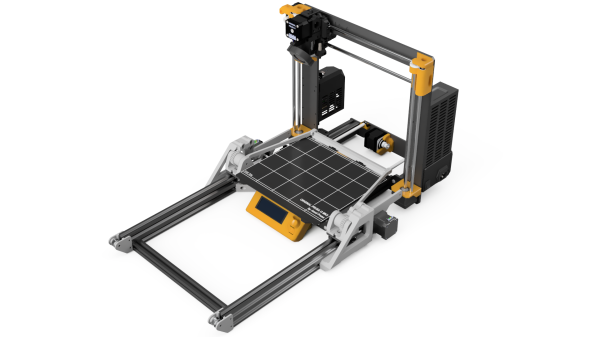
Giving a 3D printer the ability to remove its own prints means that it can crank out part after part automatically, without relying on a human operator between jobs. [Damien Weber] has done exactly that to his Prusa MK3/S printer, with what he calls the Chain Production Add-on.
[Damien]’s approach is one we haven’t quite seen before. When printing is complete, a fan cools the part then an arm (with what looks like utility knife blades attached at an angle) swings up and behind the bed. The arm zips forward and scoops the print off the bed, dumping the finished part in the process. It’s all made from 3D printed parts, aluminum extrusion and hardware, two stepper motors, and a driver PCB. The GitHub repository linked above holds all the design files, but there is also a project page on PrusaPrinters.org.
Not quite sure how it all works? Watch it in action in the video embedded below.
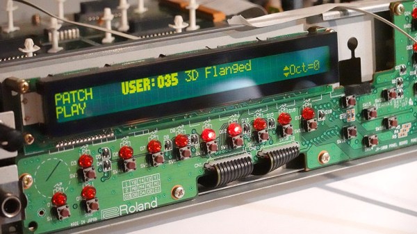
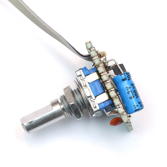
[Mitxela]’s repair of a Roland JV-1080 (a rack-mounted 90s-era synthesizer) sounds simple: replace a broken rotary encoder on the front panel. It turned out to be anything but simple, since the part in question is not today’s idea of a standard rotary encoder at all. The JV-1080 uses some kind of rotary pulse switch, which has three outputs (one for each direction, and one for pushing the knob in like a button.) Turn the knob in one direction, and one of the output wires is briefly shorted to ground with every detent. Turn it the other way, and the same happens on the other output wire. This is the part that needed a replacement.
The finished unit uses a modern rotary encoder and microcontroller in place of the original part, and implements a few tricks to power it.
Rather than track down a source for the broken part, [Mitxela] opted to replace it with a modern rotary encoder combined with an ATtiny85 microcontroller to make it act like something the JV-1080 understands and expects. There was an additional wrinkle, however. The original rotary pulse switch is an entirely passive device, and lives at the end of a four-conductor cable with no power provided on it. How could the ATtiny85 be powered without resorting to running a wire to a DC voltage supply somewhere? Success was had, but it did take some finessing.
For the power, it turns out that the signal wires are weakly pulled up to +5 V and [Mitxela] used that for a power supply to the microcontroller. Still, by itself that wasn’t enough, because the ATtiny85 can easily consume more current than the weak pullups can source. We really recommend reading all the details in [Mitxela]’s writeup, but the short version is that the ATtiny85 does two things.
First, it minimizes its power usage by spending most of its time in sleep mode (consuming barely any power at all) and uses an interrupt to wake up just long enough to handle knob activity. Second, the trickle of power from the weak pullups doesn’t feed the ATtiny directly. It charges a 100 uF capacitor through a diode, and that is what keeps the microcontroller from browning out during its brief spurts of activity. Even better, after browsing the datasheet for the ATtiny, [Mitxela] saw it was possible to use the built-in ESD protection diodes for this purpose instead of adding a separate component.
It’s a neat trick and makes for a very compact package. Visit the project’s GitHub repository to dive into the nitty gritty. In the end, a single assembly at the end of a 4-wire connector acts just like the original passive component, no extra wires or hardware modifications needed.
When opening older hardware it’s never quite certain what will be found on the inside. But at least [Mitxela]’s repair duties on this synth didn’t end up with him tripping out on LSD.