Call us crazy, but music was a whole lot more fun when it was on physical media. Or perhaps just easier to use, especially in the car. Whether your particular vintage favored CDs, cassettes, or even 8-tracks, being able to fish out that favorite album and slam it in the player while never taking your eyes off the road was a whole lot easier than navigating a playlist on a locked phone, or trying to control an infotainment system through soft buttons on a touch screen.
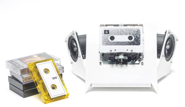
It seems like [Jarek Lupinski] is as much a Spotify Luddite as we are, since his “tape-deck” project is aimed to be as user-unfriendly as possible. It’s just an auto-reversing cassette deck movement stripped bare of all useful appurtenances, like a way to fast forward or rewind. You just put a cassette in and it plays, start to finish, before auto-reversing to play the other side in its entirety. It doesn’t even have a volume control — his cheeky advice is to “listen to louder or quieter albums” to solve that problem. Pretty easy, really, and not a EULA or advertisement in sight. Build files are available if you hate yourself enough to build one of your own.
All kidding aside, this is kind of a nice reminder of how much things have changed, and how much complexity we’ve layered onto the simplest of pleasures. If you like the minimalist approach of this project but not the deconstructed aesthetics, we’ve got you covered.