New DOS PCs, In 2023?

It’s not likely that we’ll talk about a new PC here at Hackaday because where’s the news in yet another commodity computer? But today along comes not one but two new PCs courtesy of the ever bounteous hall of wonders at AliExpress, that are unusual enough to take a look at. If you have around $250 to spare, you can have a brand new, made in 2023, 80386sx plamtop PC capable of running Windows 95, or an 8088 laptop for DOS. Just what on earth is going on?

Continue reading “New DOS PCs, In 2023?”

An Open-Source 4-Shaft Portable Loom

Part of writing for Hackaday involves doing the rounds of our community’s events in search of amazing projects for your delectation. This weekend it was a trip to Maker Faire Delft, thanks to the wonders of the European Interail scheme. Once on the site, [Aslı Aydın Aksan]’s 4-shaft weaving loom immediately caught our eye. This is an open-source portable folding loom design. In weaving terms, shafts are sliding vertical frames. As the name implies, this loom has four, which allow different sets of warp threads to be brought to the surface of the weave at different times. This feature makes it capable of weaving complex patterns in the fabric and thus makes it a very interesting project indeed.

The frame of the loom is laser-cut ply, cunningly designed such that when not in use it can be folded into a compact unit. The attachments are all 3D-printed PLA in the prototypes, the comb is laser-cut acrylic, and the heddles are 3D printed in a flexible material. These last components conceal a further trick, they’re designed to be extra-easy to move between shafts on the fly, allowing even more complex patterns to be created.

All in all this is one of those special projects that comes out of the blue and raises the bar on all in its class. If there’s another 4-shaft loom this accessible, we’ve yet to hear of it.

It’s not the first loom we’ve covered, however, this one wasn’t nearly as accomplished.

A Non-Destructive Digital Back For A Classic Leica

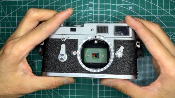
As digital photography has become so good, perhaps just too good, at capturing near-perfect pictures, some photographers have ventured back into the world of film. There they have found the imperfections requiring technical skill to cope with that they desire, but they’ve also come face-to-face with the very high cost and sometimes sketchy availability of film stocks. From this has come the so-called post-digital movement which marries analog cameras and lenses with digital sensors, and of this a particularly nice example comes from [

Perhaps the best thing about this conversion, and something which should propagate forward into other builds, is the way it does not hack or modify the original camera beyond the replacement of the already-removable back. A vintage Leica is a pricey item, so it would be a foolhardy hacker who would proceed to gut it for a digital conversion. Instead he’s mounted everything that makes a digital camera, the sensor, Pi Zero, and screen board, behind the camera body. The Pi shutter trigger comes from the Leica’s flash terminal, meaning that there’s plenty of time for it to take a photo while the shutter is open.

He’s admirably preserved the usage and properties of the Leica, and his photographs as can be seen in the video below the break bear testament to what is possible with the camera. He still has to work with the tiny sensor size though, meaning that all photographs are at a much higher zoom level than on the original. We would love to see a camera conversion like this one that incorporates appropriate lenses to bring the picture to focus on this small sensor.

We won’t own a Leica any time soon, but we like this conversion. It’s by far the most sympathetic, but it’s not the first rangefinder conversion we’ve seen.

Continue reading “A Non-Destructive Digital Back For A Classic Leica”

What Is A Schumann Resonance And Why Am I Being Offered A 7.83Hz Oscillator?

Something that probably unites many Hackaday readers is an idle pursuit of browsing AliExpress for new pieces of tech. Perhaps it’s something akin to social media doomscrolling without the induced anger, and it’s certainly entertaining to see some of the weird and wonderful products that can be had for a few dollars and a couple of weeks wait. Every now and then something pops up that deserves a second look, and it’s one of those that has caught my attention today. Why am I being offered planar PCB coils with some electronics, described as “Schumann resonators”? What on earth is Schumann resonance, anyway? Continue reading “What Is A Schumann Resonance And Why Am I Being Offered A 7.83Hz Oscillator?”

USB Meets Core Memory In A Vintage ‘Scope

It’s normal today for even relatively modest instruments to have some form of computer control capability over Ethernet or USB. But five decades ago this was by no means a given, and when Tektronix shipped their P7001 digitiser module for their high-end oscilloscopes in 1971, they were initially designed to interface with a minicomputer. Not everybody has a PDP/11 lying around in 2023, but [Holger Lübben] wasn’t fazed by this. He set about creating a USB interface for this ancient piece of test equipment.

At its heart is a Teensy 4.1 which does the job of interfacing with the Tektronix 16-bit bus through a level shifting transceiver. The software for the Teensy comes with some demos, but sadly not the Tek BASIC of the original. We’re particularly impressed with the care to make the card frame for the module resemble as closely as possible an original Tektronix product.

We’re guessing very few of you will have this ancient test module on your bench, but the depth into which he goes over its internal design and programming makes this very much worth a read. If you fancy more vintage Tek goodness, take a look at this current probe.

Op-Amp Challenge: Compare Op-Amps, By Listening To Them

In the world of audiophilia there are arguments that rage over the relative merits of particular components. Sometimes this can reach silly levels as in the high-end ALPS pot we once saw chosen as a volume control whose only task was to be a DC voltage divider feeding a pin on a DSP, but there are moments where such comparisons might have a bit of merit. To allow the comparison of different op-amps in a headphone amplifier, [Stephan Martin] has created a stereo amplifier board complete with sockets to take single or dual op-amp chips.

The circuit is based upon a design from the 1990s which as far as we can see is a pretty conventional non-inverting amplifier. It has an on-board op-amp to create a virtual ground, and three sockets for either two single or one dual op-amp to create a stereo headphone amplifier.

So the burning question is this: will you notice a difference? We’re guessing that assuming the op-amps under test are to a sufficient specification with a high enough impedance input and enough output current capability, the differences might be somewhat imperceptible without an audio analyser or the hearing of a ten-year-old child.

Need more of an audio fix? Try our Know Audio series.


Op-Amp Challenge: A Low Noise Amplifier For Those Truly Low Noise Measurements

When something is described as “Low Noise”, it is by the nature of the language a relative phrase. The higest quality magnetic tape is low noise compared to its cheaper sibling for example, but still has noise many would consider unacceptable. In instrumentation however, “Low Noise” has to really mean just that, with a range of specialist techniques to produce circuitry with a truly low noise level for the most demanding of signal applications. As an example [Floydfish] has created a low noise instrumentation amplifier that should serve as a learning exercise for anyone interested in pushing low noise circuitry to the limit.

Anyone who can dredge the hazy recesses of their mind for barely-remembered electronics lectures will know that the overall noise figure of a system is dictated by that of its first component. Thus perhaps the most interesting part of the schematic is at the input, where a row of low-noise op-amps are presented in parallel. We have to admit having to look this one up, to find that it’s a technique whereby the signal outputs of each chip are the same and thus sum, while the noise output of each is different and thus the summed noise output is proportionally lower. This stage is then followed by a buffer and a set of filters for different output frequency ranges.

Our op-amp competition of which this is a part is certainly delivering the goods when it comes to the amny techniques with which these versatile parts can be used. Few of us may need to make such a low noise amplifier, but at least now we’ve learned how.