A problem facing architects when designing complex three-dimensional structures lies in their joints, which must be strong enough to take the loads and vector forces applied by the structure, yet light enough not to dominate it. Many efforts have been made to use generative design techniques or clever composites to fabricate them, but as Dezeen reports, a team at MIT are exploring an unexpected alternative in the form of naturally occurring tree forks.
The point at which a tree branch forks from its trunk is a natural composite material formed of an interlocking mesh of wood grain fibres. Timber processors discard these parts of the tree as they interfere with the production of smooth timber, but the same properties that make them support the weight of a branch are it seems perfect for the architects’ needs.
The clever part of the MIT team’s work lies in scanning and cataloguing a library of forks, allowing them to be matched from the database to vertices in an architectural design. The forks are subject to minimal machining before being incorporated into the structure, and to prove it the MIT folks have made a test structure. It’s not uncommon to see medieval barns or half-timbered houses using curved pieces of wood in their natural shapes, so it’s not surprising to see that this 21st century innovation isn’t an entirely new technique.
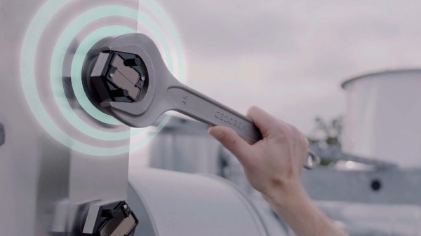
The bane of life for anyone who possesses a well-used pile of spanners is the humble nut and bolt. Durable and easy to fasten, over our lifetimes we must screw and unscrew them by the million. When they do their job they’re great, but too often they seize up solid, or more alarmingly, gradually undo themselves over time due to vibration or thermal stress. There are a host of products such as locking nuts or thread sealant to deal with this problem, but the Fraunhofer Institute have an idea which might just remove the worry surrounding important fastenings. Their work has resulted in a solar-powered bolt with an embedded sensor that phones home when the connection loosens, allowing an engineer to be dispatched with a spanner to tighten it up.
The sensor itself is a washer which reports the force placed upon it, when this reduces an alert is sent. Communication is via Fraunhofer’s own MIoTy low-power wide-area network (LPWAN) protocol, but we’d imagine that one of the many competitor technologies could also serve.
This is an interesting idea that could no doubt result in targeted maintenance catching faulty fastenings early and averting disaster in the infrastructure projects such as bridges and wind turbines that they mention. We worry slightly though, because these types of structures have lives not in the few years of most tech products but in centuries. Will an IoT bolt head sensor still be phoning home in a few decades time, or will the system rely on old bolts being replaced at regular intervals of a decade? It’s not unknown for disasters to be the result of failures in fastenings a century old, so we sincerely hope that authorities in charge of whatever bridge relies on these won’t be tempted to skimp on their replacements. Perhaps a guy with a spanner every few years might be a more dependable option.
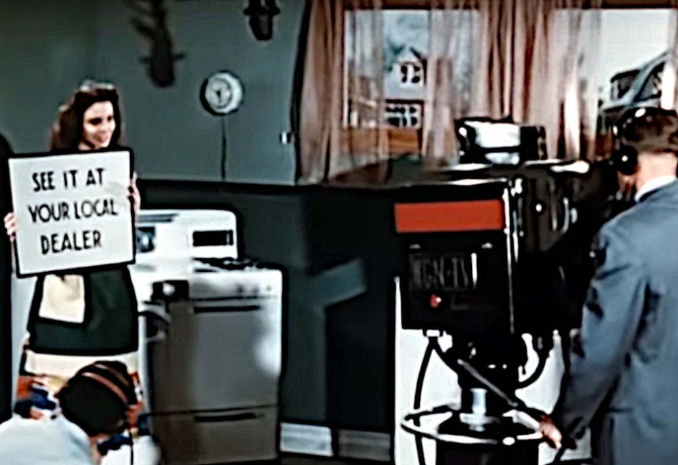
Watching television today is a very different experience from that which our parents would have had at our age, where we have high-definition digital on-demand streaming services they had a small number of analogue channels serving linear scheduled broadcasting. A particular film coming on TV could be a major event that it was not uncommon for most of the population to have shared, and such simple things as a coffee advert could become part of our common cultural experience. Behind it all was a minor miracle of synchronised analogue technology taking the signal from studio to living room, and this is the subject of a 1952 Coronet film, Television: How It Works! Sit back and enjoy a trip into a much simpler world in the video below the break.
Production values for adverts had yet to reach their zenith in the 1950s.
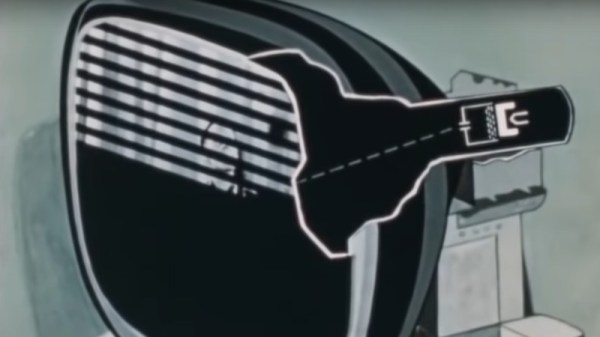
After an introduction showing the cultural impact of TV in early-50s America there’s a basic intro to a cathode-ray tube, followed by something that may be less familiar to many readers, the Image Orthicon camera tube that formed the basis of most TV signals of that era.
It’s written for the general public, so the scanning raster of a TV image is introduced through the back-and-forth of reading a book, and then translated into how the raster is painted on the screen with the deflection coils and the electron gun. It’s not overly simplified though, for it talks about how the picture is interlaced and shows how a synchronisation pulse is introduced to keep all parts of the system working together.
A particularly fascinating glimpse comes in a brief mention of the solid copper co-axial cable and overland microwave links used to transmit TV signals across country, these concrete towers can still be seen today but they no longer have the colossal horn antennas we can see in the film.
A rather obvious omission in this film is the lack of any mention of colour TV, as while it would be late 1953 before the NTSC standard was formally adopted and early 1954 before the first few colour sets would go on sale. Colour TV would have been very much the Next Big Thing in 1952, but with no transmissions to watch and a bitter standards war still raging between the field-sequential CBS system and RCA’s compatible dot-sequential system that would eventually evolve into the NTSC standard it’s not surprising that colour TV was beyond the consumer audience of the time.
Thus we’re being introduced to the 525-line standard which many think of as NTSC video, but without the NTSC compatible colour system that most of us will be familiar with. The 525-line analogue standard might have disappeared from our living rooms some time ago, but as the last few stations only came off-air last year we’d say it had a pretty good run.
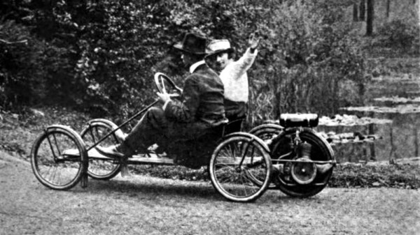
A couple of years ago, Hackaday published an article, “Electric Vehicles Continue the Same Wasteful Mistakes That Limit Longevity“, in which we took a look at the way the car industry, instead of taking the move to electric traction as an opportunity to simplify their products, was instead making their electric offerings far more complex. It touched a nerve and received a very large comment volume, such that now it is our 19th most commented story of all time.
It’s something brought back to the fore by seeing a The Drive piece bemoaning the evolution of the automobile as a software receptacle governed by end-user licenses rather than a machine under the control of its owner. In turn that’s posed the question: Just what do you really need for a car, and what is superfluous? Time to provide an answer to that question, so here it is: a minimal motoring manifesto. Continue reading “A Minimal Motoring Manifesto”→
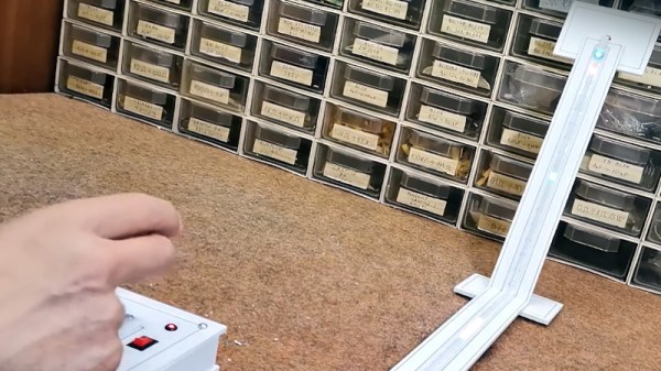
Under the Hackaday TV is a modern game console, it’s a well-known model that many of you also probably have, and its main feature is a 3D accelerator which allows it to create the beautifully rendered worlds we’ve all come to know and love. [Mircemk] eschews such fripperies with the Twang project, because it’s a game that’s not 3D, nor 2D, but 1D. The display, indeed the entire gaming surface, is a single strip of addressable LEDs which can be seen int he video below the break.
Behind it all is an ESP32, and a unique one-dimensional joystick using an accelerometer. There’s an audio channel with a little piezoelectric speaker too, and the LED strip is a particularly high-density one from DFRobot. Because this is an ESP32-driven device it has WiFi, upon which is exposed an access point for a network over which is served the game stats as a web page. It may not displace that modern console, but it’s certainly inventive.
As spring slowly slides into summer here in Europe where this is being written, the warm weather is a reminder that on the horizon are the summer’s crop of hacker camps. The largest European one this year will be the Dutch MCH2022 near the end of July, and to whet our appetite they’ve made public some details of their badge. And true to the past form of Dutch camps, it’s rather an impressive build.
Since this is another piece of work from badge.team it has the expected ESP32 module, but alongside it on the elegantly-designed PCB there’s an RP2040 and a Lattice ICE40UP5K FPGA. The ESP is there to run the badge team firmware which even includes backwards compatibility with the original SHA2017 badge, the RP2040 ties everything together and provides a multitude of USB peripherals, and the FPGA is there to run user code. From the front, the badge has a Game Boy Advance-style form factor with a large colour TFT screen and the usual joystick and buttons. Other peripherals include a brace of addressable LEDs, a pair of nifty sensors from Bosch, and a 16-bit stereo audio channel that even powers a small onboard mono speaker when no headphones are connected.
The hardware may be slick, but it’s the badge.team firmware that makes this as special as all their previous offerings. It offers the chance to easily write apps either in MicroPython for the ESP32, or as payloads for the FPGA, and what makes it special is that it comes with an online app store from which all the apps can be downloaded. We’re told that it will be able to run a range of emulators out of the box, so we’re really looking forward to seeing the final version at the event. Meanwhile they’ve released a demo video that you can see below the break, and if you’re curious you can take a look at its SHA2017 badge ancestor.
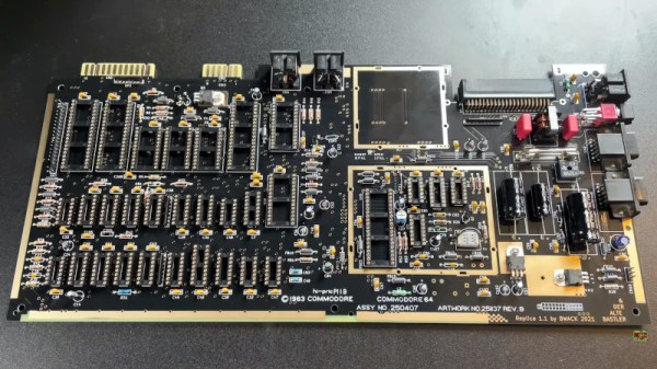
The Commodore 64 remains one of the most influential of the 8-bit home computers four decades after its launch, so not surprisingly there is a huge enthusiast community surrounding it. With so many produced over the years it was available one might think that there would be no shortage of surviving specimens, but sadly time and component failure have taken their toll and the classic micro is not always the most reliable kid on the block. Thus a cottage industry has sprung up supplying C64 parts, leading [The Retro Shack] to have a go at making a new one entirely from scratch.
As you can see in the video below the break it’s not quite an entirely new ’64, as parts including some of the custom silicon come from failed boards. The PCB is a modern recreation of the original and the SID sound chip is an ARMsid though, and most of the parts come from a handy bagged-up kit that makes assembling the BoM much easier. Instead of the big silver box of the original RF modulator is a modern composite board, and there are a few issues with minor connector part differences.
Assembly is simply a very long through-hole soldering process, and once he’d completed it there was the expected refusal to work. We’ve all been there, and eventually he traced it to an incorrectly fitted chip. If you think you’ve seen a few brand new C64s here before you’d be correct, one of them even used LEGO for those elusive keycaps.