Flashing An LED The Widlar Way

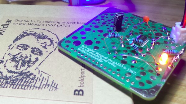
Regular Hackaday readers will be familiar with the work of Boldport’s [Saar Drimer] in creating beauty in printed circuit board design. A recent work of his is the Widlar, a tribute to the legendary integrated circuit designer [Bob Widlar] in the form of a development board for his μA723 voltage regulator chip.

The μA723 is a kit of parts from which almost any regulator configuration can be made, but for [tardate]  it represented a challenge. The μA723 is so versatile that what you can create is only limited by the imagination of the builder. Having done the ordinary before, [tardate] looked toward something unconventional.
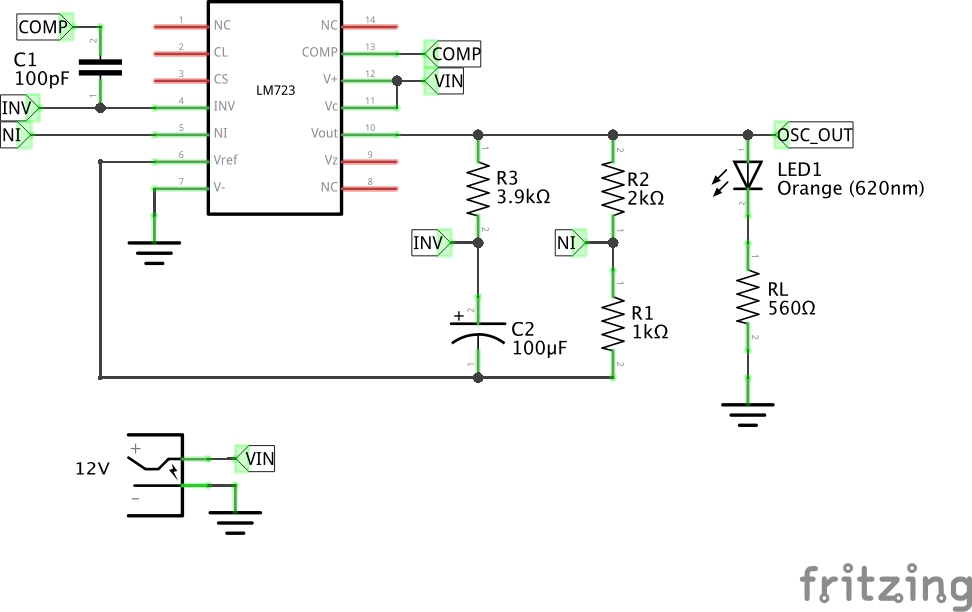
The result is modest, a simple LED flasher using the error amplifier as a not-very-good op-amp, building an oscillator at a frequency of about 2 Hz. This is pretty neat and if you are used to the NE555 as the universal integrated circuit, perhaps it’s time to set it aside for the obviously far-more-useful μA723.

Here at Hackaday we harbour at least one fan of the μA723, not to mention also of artful PCBs. If the Widlar looks familiar, we featured the switch mode regulator from the μA723 data sheet on it a few months ago.

Disclosure: [Jenny List] wrote the documentation for Boldport’s Widlar kit.

Biasing That Transistor: The Common Base Amplifier

We’ve previously remarked upon a generation lucky enough to be well-versed in microcontrollers and computersised electronics through being brought up on the Arduino or the Raspberry Pi but unlucky enough to have missed out on basic electronics such as how to bias a transistor, and to address that gap we’ve taken a look at the basics of transistor biasing.

All the circuits we worked with in the previous article had the transistor’s emitter taken to ground, took their input from the base, and their output from the collector. This configuration, called a Common Emitter amplifier is probably the most common, but it is far from the only way to use a transistor. Once you have set up the bias voltage as we described to the point at which the transistor is in its linear region, there are several other ways in which the device can be used as an amplifier. The subject of this article is one of these configurations, so described because it takes the transistor’s base to the ground instead of the emitter, as a Common Base amplifier. Continue reading “Biasing That Transistor: The Common Base Amplifier”

Double The Resolution, From An Arduino ADC

Analog-to-digital converters, or ADCs, are somewhat monolithic devices for most users, a black box that you ask nicely for the value on its input, and receive a number in return. For most readers, they will be built into whatever microcontroller is their platform of choice, and their resolution will be immutable, set by whatever circuitry is included upon the die. There are a few tricks that can be employed to get a bit more from a stock ADC though, and [Neris] has taken a look at a couple of them.

The first circuit doubles the resolution of an ADC, in this case, that of the Atmel chip in an Arduino, by converting its output from an integer to a signed integer. It performs this task with a precision rectifier, rectifying around a zero-crossing point half-way through the range of the analog value to be read and supplying a sign bit to the Arduino. The Arduino measures the rectified analog value to an integer, and applies the appropriate sign from the supplied bit value.

The second circuit takes a variation on the same technique but with two ADCs instead of one. A pair of PIC chips are used with their voltage references stacked one above the other, by taking both readings in combination a result with double the resolution can be derived.

You might ask why bother with these techniques. After all, there are plenty of higher-resolution ADCs on the market. But they’re useful techniques to know, should you ever need to extract the proverbial quart from a pint pot.

If ADCs are a mystery to you, you’re in luck. [Bil Herd] gave us a comprehensive introduction to the subject.

Fail Of The Week: Never Assume All Crystals Are Born Equal

You should be used to our posting the hacks that didn’t quite go according to plan under our Fail Of The Week heading, things that should have worked, but due to unexpected factors, didn’t. They are the fault, if that’s not too strong a term, of the person making whatever the project is, and we feature them not in a spirit of mockery but one of commiseration and enlightenment.

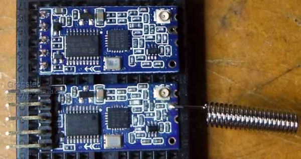
This FOTW is a little different, because it reveals itself to have nothing to do with its originator. [Grogster] was using the widely-available HC-12 serial wireless modules, or clones or even possibly fakes thereof, and found that the modules would not talk to each other. Closer inspection found that the modules with the lack of intercommunication came from different batches, and possibly different manufacturers. Their circuits and components appeared identical, so what could possibly be up?

The problem was traced to the two batches of modules having different frequencies, one being 37 kHz ahead of the other. This was in turn traced to the crystal on board the off-frequency module, the 30 MHz component providing the frequency reference for the Si4463 radio chip was significantly out of spec. The manufacturer had used a cheap source of the component, resulting in modules which would talk to each other but not to the rest of the world’s HC-12s.

If there is a lesson to be extracted from this, it is to be reminded that even when cheap components or modules look as they should, and indeed even when they appear to work as they should, there can still be unexpected ways in which they can let you down. It has given us an interesting opportunity to learn about the HC-12, with its onboard STM8 CPU and one of the always-fascinating Silicon Labs radio chips. If you want to know more about the HC-12 module, we linked to a more in-depth look at it a couple of years ago.

Thanks [Manuka] for the tip.

Biasing That Transistor: The Common Emitter Amplifier

If you open up the perennial favourite electronics textbook The Art Of Electronics and turn to the section on transistors, you will see a little cartoon. A transistor is shown as a room in which “transistor man” stands watching a dial showing the base current, while adjusting a potentiometer that limits the collector current. If you apply a little more base current, he pushes up the collector a bit. If you wind back the base current, he drops it back. It’s a simple but effective way of explaining the basic operation of a transistor, but it stops short of some of the nuances of how a transistor works.

Of course the base-emitter junction is a diode and it is not a simple potentiometer that sits between collector and emitter. The “better” description of these aspects of the device fills the heads of first-year electronic engineering students until they never want to hear about an h-paramater or the Ebers-Moll model of transistor function again in their entire lives. Fortunately it is possible to work with transistors without such an in-depth understanding of their operation, but before selecting the components surrounding a device it is still necessary to go a little way beyond transistor man.

Continue reading “Biasing That Transistor: The Common Emitter Amplifier”

More Details On That First Home-Made Lithographically Produced IC

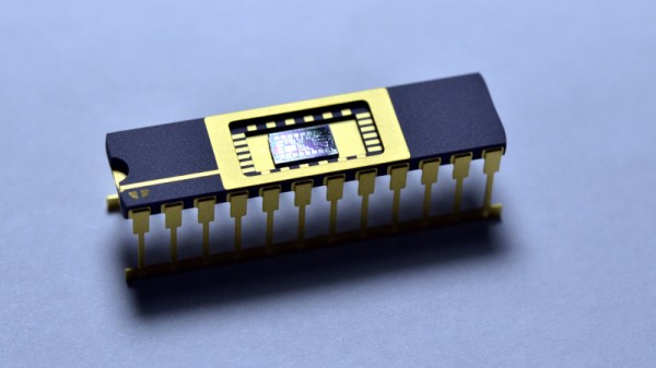
A few days ago we brought you news of [Sam Zeloof]’s amazing achievement, of creating the first home-made lithographically produced integrated circuit. It was a modest enough design in a simple pair of differential amplifiers and all we had to go on was a Twitter announcement, but it promised a more complete write-up to follow. We’re pleased to note that the write-up has arrived, and we can have a look at some of the details of just how he managed to produce an IC in his garage. He’s even given it a part number, the Zeloof Z1.

For ease of manufacture he’s opted for a PMOS process, and he is using four masks which he lists as the active/doped area, gate oxide, contact window, and top metal. He takes us through 66 different processes that he performs over the twelve hours of a full production run, with comprehensive descriptions that make for a fascinating run-down of semiconductor manufacture for those of us who will never build a chip of our own but are still interested to learn how it is done. The chip’s oblong dimensions are dictated by the constraints of an off-the-shelf Kyocera ceramic chip carrier, though without a wire bonding machine he’s unable to do any more than test it with probes.

You can read our reporting of his first announcement, but don’t go away thinking that will be all. We’re certain [Sam] will be back with more devices, and can’t wait to see the Z2.

Auction Finds Combined For A Unique Desoldering Station

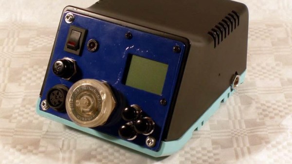
If you are in the market for a high-quality soldering iron, a rewarding pursuit can be attending dispersal auctions. It is not unusual to see boxes of irons, as anything remotely iron-like is bundled up together by the auctioneer into a lot with little consideration for what combination has been gathered. [Stynus] found himself in this position, the proud owner of a Weller DSX80 desoldering iron from an auction, but without its accompanying solder station required for it to work. Fortunately, he had another Weller solder station, not suitable for the DSX80 as it stood, but which provided a perfect platform for a home-made Weller DSX set-up.

The old station had a side-mounted valve and a 24V input, so he had to install a toroidal mains transformer and move the valve frontwards. Fortunately, this style of Weller station case was frequently available with just such a transformer installed, so there was plenty of space in the enclosure. A custom board was then created for a temperature controller centered upon a PIC microcontroller, and a new front panel was crafted to accommodate a Nokia 5110-style LCD display.

The resulting unit with its upper half repainted, is a pleasing and professional-looking project. Heated desoldering irons are an extremely useful tool that anyone should consider for their arsenal, but not all of them are as good as this Weller-based one. We recently reviewed a much cheaper example, with comedic results.