Building A Half Toy Half Model Tank Robot

For some, the idea of several hours of painting and designing intricate models with minute details and features sounds like a delightful afternoon spent. Some of us would much rather just have it come already painted with motors so that it can move. [Cory Collins] sought to combine these two hobbies by building a highly detailed motorized tank dubbed Tankbot 2.3. (Video, embedded below.)

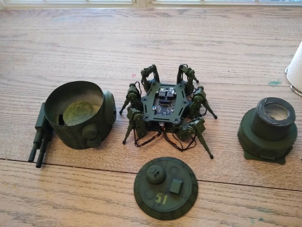
It’s based on a simple hexapod kit ordered online that includes a built-in Arduino compatible board (it’s based on the Arduino 2560 Mega). The legs were redesigned to match the aesthetic that [Cory] was going for. The redesign allows for an extra pivot in the leg mechanism. The turret section was designed and built on top of the base with support for a servo to turn it (though the firmware isn’t quite there yet). After all the parts were 3d printed, the laborious process of painting began. With some delicate airbrushing and some quick stencils cut for the decals, it was complete.

We are amazed by the types of kits and parts that you can find online and the fact that they’re usually inexpensive to boot. We’ve come a long way since 2013 when we covered a much simpler Arduino based tank.

Continue reading “Building A Half Toy Half Model Tank Robot”

Recreating The Mac SE Logic Board

When [Kai Robinson] found himself faced with the difficult task of saving as many Mac SE’s as he possibly could, the logical but daunting answer was to recreate the Mac SE logic board for machines that would otherwise be scrapped. These machines are over 30 years old and the PRAM battery often leaks, destroying parts and traces. Given that the logic board is a simple through-hole two four-layer board, how hard could it be?

The first step was to get some reference photos so [Kai] set to desoldering everything on the board. The list of components and the age of solder made this an arduous task. Then a composite image was produced by merging images together using a scanner and some Inkscape magic. in graphics software.

Rather than simply putting the pins in the right place and re-routing all the netlists, [Kai] elected instead to do a copy, trace for trace of the original SE board. [Kai] and several others on the forum have been testing the boards and tracking down the last few bugs and kinks in the design. An unconnected pin here and an improperly impedance matched resistor there. Hopefully, soon they’ll have Gerbers and design files ready for anyone should they need a new logic board PCB.

It’s no secret that we love the Macintosh SE here at Hackaday. We’ve seen new custom cases for it and now new PCBs for it. It does cause the mind to ponder though and wonder, what’s next?

Thanks [Toru173] for sending this one in!

Add An Extra 8GB Of VRAM To Your 2070

Most of us make do with the VRAM that came with our graphics cards. We can just wait until the next one comes out and get a little more memory. After all, it’d be madness to try and delicately solder on new components of something so timing-sensitive as RAM chips, right?

[VIK-on] took it upon himself to do just that. The inspiration came when a leaked diagram suggested that the RTX 2000 line could support 16 GB of RAM by using 2GB chips. NVIDIA never did release a 16GB version of the 2070, so this card is truly one of a kind. After some careful scouring of the internet, the GDDR6 chips were procured and carefully soldered on with a hot air gun. A few resistors had to be moved to accommodate the new RAM chips. During power-on, [VIK-on] saw all 16 GB enumerate and was able to run some stress tests. Unfortunately, the card wasn’t stable and started having black screen issues and wonky clocks. Whether it was a bad solder joint or firmware issues, it’s hard to say but he is pretty convinced it is a BIOS error. Switching the resistors back to the 8GB configuration yielded a stable system.

While a little more recent, this isn’t the only RAM upgrade we’ve covered in the last few months. Video after the break (it’s not in English but captions are available).
Continue reading “Add An Extra 8GB Of VRAM To Your 2070”

Learning To Speak Peloton

Recently [Imran Haque]’s family bought the quite popular Peloton bike. After his initial skepticism melted to a quiet enthusiasm, [Imran] felt his hacker curiosity begin to probe the head unit on the bike. Which despite being a lightly skinned android tablet, has a reputation for being rather locked down. The Peloton bike will happily collect data such as heart rate from other devices but is rather reticent to broadcast any data it generates such as cadence and power. [Imran] set out to decode and liberate the Peleton’s data by creating a device he has dubbed PeloMon. He credits the inspiration for his journey to another hacker who connected a Raspberry Pi to their bricked exercise bike.

As a first step, [Imran] step began with decoding the TRRS connector that connects the bike to the head unit. With the help of a multi-meter and a logic analyzer, two 19200bps 8N1 RS-232 channels (TX and RX) were identified. Once the basic transport layer was established, he next set to work decoding the packets. By plotting the bytes in the packets and applying deductive reasoning, a rough spec was defined. The head unit requested updates every 100ms and the bike responded with cadence, power, and resistance data depending on the request type (the head unit did a round-robin through the three data types).

Once the protocol was decoded, the next step for [Imran] was to code up an emulator. It seems a strange decision to write an emulator for a device with a simple protocol, but the reasoning is quite sound. It avoids a 20-minute bike ride every time a code change needs to be tested. [Imran] wrote both an event-driven and a timing-accurate emulator. The former runs on the same board as the PeloMon and the latter runs on a separate board (an Arduino).

The hardware chosen for the PeloMon was an Adafruit Feather 32u4 Bluefruit LE. It was chosen for supporting Bluetooth LE as well as having onboard EEPROM. A level shifter allows the microcontroller to talk directly to the RS-323 on the bike. After a few pull requests to the Adafruit Bluetooth libraries and a fair bit of head-banging, [Imran] has code that advertises two Bluetooth services, one for speed and another for power. A Bluetooth serial console is also included for debugging without having to pull the circuit out.

The code, schematics, emulators, and research notes are all available on GitHub.

Turning A CMM Into A 3D Printer

There are two paths to owning a 3D printer: purchasing one or crafting your own 3D printer designed to your own exacting specifications. [Roetz 4.0] has decided to go this latter route and converted a 1.3-ton air-bearing Coordinate-measuring machine (CMM) into an FDM 3D printer. (Video, embedded below.)

A CMM is a tool used to precisely measure the geometry of an object via gently lowering a calibrated probe. We’ve seen scratch build printers before, but this particular build benefits from having the CMM machinery and its 18 air bearings. The CMM head is moved by [Roetz 4.0]’s own custom system, but it takes advantage of the bearings. After some careful CAD planning as well as a fair bit of milling, lathing, and prototyping, he had buttery smooth controlled motion.

With an off the shelf driver board wired together with a large red button, he was ready for a maiden test print. A determination to finish before the year was out pushed things along. There are still a few quirks to fix, like the hole in the air drying system but those can be tackled next year. Ultimately, we think the results are stunning and it was a journey we were glad to go on with [Roetz 4.0]. The final episode of the series is after the break.

Continue reading “Turning A CMM Into A 3D Printer”

76-bit Trombones Led By The Big MIDI File

Inspired by the creative genius of Martin Molin of Wintergatan fame, [iSax] set out to create a robotic MIDI-controlled trombone. It takes years for humans to develop the control and technique required to play the trombone well as the tone produced into the mouthpiece (embouchure) is a tricky combination of air pressure, lip tension, airflow, resonance in the mouth, and other sources of complex pressure.

[iSax] gives a thorough walkthrough of the machine, which is powered by two separate sources of air, one for the position of the slide and the other for producing sound. A potentiometer provides feedback on the position of the slide and a servo controls the flow rate into the silicone resonance chamber. The chamber can be tuned via a stepper motor that applies pressure, slightly altering the chamber’s frequency and pressure. An Arduino with Firmata allows the device to controlled easily from any host computer. A detailed writeup in PDF form is on the Hackday.io project page.

As you can imagine, simulating a human mouth is a daunting task and the number of variables meant that [iSax] ended up with something only vaguely trombone-like. While ultimately it didn’t turn out to be the astounding music machine that [iSax] hoped, it did end up being a fun feat of engineering we can appreciate and admire. Progress towards automatic brass instruments seems to be coming slowly as we saw similar results with this robotic trumpet. Maybe someday we’ll have robot brass sections, but not today.

Continue reading “76-bit Trombones Led By The Big MIDI File”

Racing The Old Clock

[Keenan Rebera] recently found himself with an old racing clock (a chronoix cc3000) left behind by a roommate. How the roommate obtained such a clock seems murky at best, but undeterred [Keenan] set to work bringing the clock to life with Bluetooth functionality. The mechanical nature of the digits provided a satisfying auditory click, making it a good candidate for some upgrading. The new brain transplant is the venerable ESP32 with an RTC for good measure. He created a custom PCB with QWIC connectors to daisy chain together the driver boards together. Each PCB has four TBD62083 for driving the digits, two MCP expanders to increase the address space. This allows the ESP32 to address all the various segments over I2C. By soldering different pads together, he can change the address of each MCP, giving a maximum of 16 digits (9 possible MCP’s each driving 2 digits).

A handsomely designed app accompanies the clock, making updating the RTC and setting the timezone a breeze. Currently, it is displaying a count down to the time when 2020 is officially over. While 2020 will certainly go down in the books as a tumultuous year, it was a great year for DIY clocks at Hackaday. Just in the past few weeks, we’ve seen big LED workshop clocks, esoteric domino clocks, and beautiful clocks that double as works of art. Come 2021, we’re quite confident that [Keenan] will still have a gorgeous clock on his wall ticking and clicking away.
Continue reading “Racing The Old Clock”