We don’t have to tell the average Hackaday reader that the last two years have represented a serious dry spell for the type of in-person events that our community has always taken for granted. Sure virtual hacker cons have their advantages, but there’s nothing quite like meeting up face to face to talk shop with like-minded folks and checking out everyone’s latest passion project.
Luckily for classic computer aficionados, especially those on the East Coast of the United States, the long wait is about to end. After being forced to go virtual last year, Vintage Computer Festival East will once again be opening their doors to the public from October 8th to the 10th at the InfoAge Science & History Center in Wall, New Jersey. Attendees will need to wear a mask to gain access to the former Camp Evans Signal Corps R&D laboratory, but that’s a small price to pay considering the impressive list of exhibits, presentations, and classes being offered.
In fact, it’s shaping up to be the biggest and best VCF East yet. The Friday classes cover a wide range of topics from CRT repair to implementing a basic video controller with a FPGA, and the list of speakers include early computer luminaries such as Michael Tomczyk, the Product Manager for the VIC-20, and Adventure International founder Scott Adams. A little birdie even tells us that if you bring your copy of Back into the Storm, our very own Bil Herd will be sign it for you after his talk on the history of the Commodore wraps up Saturday evening.
 If you’d rather get hands-on you can always take a walk over to the Computer Deconstruction Laboratory, InfoAge’s on-site hackerspace. Glitch Works will be on hand with several popular kits such as the XT-IDE, an 8-bit ISA adapter that lets you connect (relatively) modern drives to classic machines, and the R6501Q/R6511Q Single Board Computer. A bit rusty with the iron and would rather start on something a little easier? Not to worry. Neil Cherry, a staple of the Hackaday comment section since before we switched to color pictures, will be instructing hackers young and old in the ways of the flux during his all-day soldering classes.
Of course, no VCF trip is truly complete until you’ve searched for treasure in the consignment room. The space has been expanded for 2021, and considering how long folks have had to clean out their attics and garages thanks to the pandemic, we’re expecting a bumper crop of interesting hardware to wade through. If the turnout for the VCF Swap Meet in April was any indication, we’d suggest bringing some extra cash with you.
As a proud sponsor of the 2021 Vintage Computer Festival East, Hackaday will naturally be bringing you a first-hand account of the overall event as well as a deeper look into some of the incredible exhibits on display in the very near future. But words and pictures on a page can only go so far. If you’ve grown tired of virtual events and are looking to peek your head out, we can guarantee a trip to InfoAge this weekend will be well worth the gas money for anyone within driving distance.
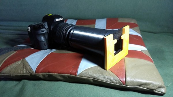
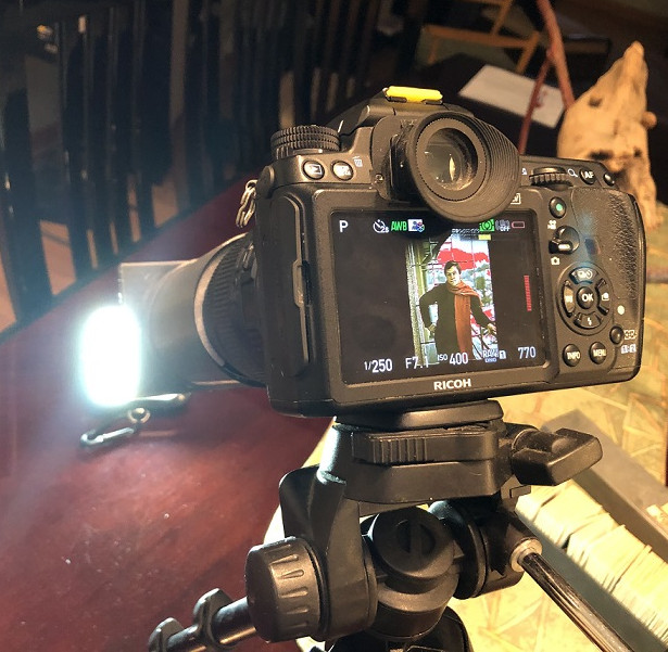 The idea is simple enough, you place the slide inside the adapter, get your focus right, and snap a picture. But of course, you’ve also got to provide some illumination. In this case, the camera is mounted on a tripod and pointed at an appropriate light source. Once you’ve experimented a bit and got the image backlit the way you want it, you can lock everything in place and easily power through a stack of vintage family memories in no time.