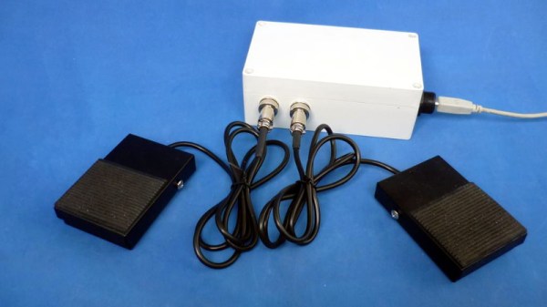
With its copious number of GPIO pins and native USB, the Raspberry Pi Pico is arguably the ideal microcontroller for developing your own platform agnostic USB Human Input Devices. But you don’t have to take our word for it. Check out how quickly the $4 USD board allowed [Alberto Nunez] to put together a pair of foot pedals for his computer.
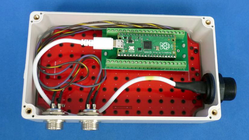
A peek inside the enclosure reveals…well, not a whole lot. All that’s hiding inside that heavy-duty plastic box is the Pi Pico and some screw down terminals that let [Alberto] easily wire up the female bulkhead connectors for the pedals themselves. Incidentally, while you could certainly make your own pedals, the ones used for this project appear to be the sort of commercially available units we’ve seen used in similar projects.
With the hardware sorted, [Alberto] just needed to write the software. While he could have taken the easy way out and hard coded everything, we appreciate that his CircuitPython script loads its configuration from a text file. This allows you to easily configure which GPIO pins are hooked up to buttons, and what key codes to associate them with. He didn’t really need to go through this much effort for his own purposes, but it makes the project far easier to adapt for others, so our hats off to him.
If you’re looking for a bit more inspiration, our very own [Kristina Panos] put together a Python-powered macro foot stool that you can put under your desk for rapid fire keyboard shortcuts. Plus you can stand on it to reach the top shelf, if need be.