Logic Analyzers For FPGAs: A Verilog Odyssey

Sometimes you start something simple and then it just leads to a chain reaction of things. I wanted to write a post about doing state machines in Verilog and target the Lattice iCEstick board that we often use for quick FPGA projects. That led to a small problem: how do you show what’s going on inside? In this series of posts, we’ll look at building a logic analyzer into an FPGA to help debug itself, instantiating memory, and — finally — state machines.

Logic analysis is a common tool in FPGA development. If you use Altera, they have Signal Tap available that lets you build a simple logic analyzer into the FPGA that talks back to your PC. Xilinx has ChipScope which is about the same. Sometimes those tools either cost money or are limited in some way in the free versions. I have my sights set on a tool that can be used with the Lattice architecture.

Sure, you can ship data out on I/O pins and then use a regular logic analyzer to pick up the data. But that isn’t very handy. So I thought about writing a generic logic analyzer component. But before I did I decided to check to see if someone else had already done it.

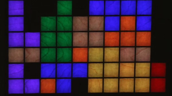
Spoiler alert: they did, but I wanted something a little different so I wound up extending the program significantly. What I wound up with is a reasonably portable Verilog logic analyzer that can produce traces like this one:

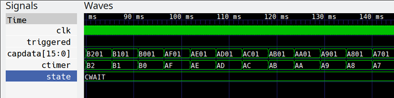
Keep in mind, this isn’t a simulation. This is real data pulled off the actual FPGA. Yes, that is gtkwave producing the plots, but the input data is a VCD file generated from samples taken inside the FPGA.

Continue reading “Logic Analyzers For FPGAs: A Verilog Odyssey”

Contest Results: Raspberry Pis Put On A Show

Some of the most satisfying projects of all are the ones that do something visual. All the network routers, data loggers, and thermostats are great. But we are visual creatures and even a humble blinking LED is enough to give you a little rush even compared to finding a large prime number. We wanted to see what our community could do visually with a Raspberry Pi so we challenged you with the Visualize it with Pi contest.

As always, the competition was brisk, with a lot of great projects. This contest showed off the trend towards using LED modules and assemblies to add visuals to projects. Why not? They are cheap enough and a well-integrated module can make a project simple to wire and integrate.

We didn’t see as many media-related projects as you might expect, although there was one tied into Stranger Things, one to Tron, and the virtual reality lighting project did have some Star Wars images. Projects ranged from the practical storage box labels to the whimsical lemonade bottle that strobes to the beat of the music. If none of that is hardcore enough for you, there was even a Raspberry Pi-controlled radio telescope. You can find all the entries over on Hackaday.io. Now let’s see which entries managed to turn the head of the judging panel.

Continue reading “Contest Results: Raspberry Pis Put On A Show”

Build Your Own LAN Cable Tester

Sure, you can buy a cable tester, but what fun is that? [Ashish] posted a nice looking cable tester that you can build with or without an onboard Arduino. If you don’t use an Arduino, the project uses a 555 chip to test the eight wires in an Ethernet cable. The readout is simple. When testing a conductor, one of 8 LEDs will light. If one doesn’t light, the cable is open. If more than one light up, there is a short. Mixed up pins will cause the LEDs to light out of sequence. You can see the device in the video below.

The 555 device is fine for the design and we were surprised that the project had provisions for using an Arduino as nothing more than a pulse generator. It could replace most of the circuit which is pretty simple. A decade counter converts the pulses into 8 pulses (a wiring change makes it reset on the 9th count). The rest of the circuit is nothing more than LEDs, resistors, and diodes.

Continue reading “Build Your Own LAN Cable Tester”

Printrbot Post Mortem

For many people, Printrbot was their first 3D printer. What started out as [Brook Drumm’s] Kickstarter idea to make 50 printers turned into over a thousand orders backlogged. To quote [Brook], they went from zero sales to about two million in the first year and then twelve million a few years later. As is often the case, though, the rapid scale-up didn’t survive a drop in sales. [Thomas Sanladerer] has a great interview video with [Brook] and you can see it below.

It is both nostalgic and sad to see the Printrbot headquarters all empty with quiet machines. [Brook] was always one of us and often gave back to the community and it is interesting to hear his perspective about what brought his company to an end.

Continue reading “Printrbot Post Mortem”

Another Drawbot Uses A Pi And Web Sockets

There’s something about art. Cavemen drew on walls. People keep programming drawing robots. One we’ve seen recently is [Andy’s] Drawbot that uses WiFi and WebSockets to draw on just about any flat surface. What’s more, the Johnson County Library has a great write-up about how they built one and if you want a go at it, you’ll find their instructions very helpful. The video below is pretty inspirational, too.

What makes this build especially interesting is that it uses a drive system with two fixed points attached with suction cups.  There are a variety of 3D printed parts — some just for the build and some are older parts repurposed.

Continue reading “Another Drawbot Uses A Pi And Web Sockets”

The Bells! The Bells! One Battery Since 1840

It is good advice to change batteries in your fire alarms at least once a year. Even our low-power LCD calculators need new batteries from time to time. But at the University of Oxford, they have an electric bell that has been ringing essentially non-stop on one set of batteries for about 178 years! Is the energy crisis solved then? Perhaps not. The bells require a high voltage but very little current and the pair of batteries — piles in the parlance of 1840 — have kept the charge flowing for about 10 billion rings. As you can see in the video below, though, the ringing isn’t very vigorous.

How does it work? When you think of converting electrical power to mechanical motion you probably think of a motor, even though there are plenty of other transducers like speakers, muscle wires, and solenoids. Arguably the first device was electrostatic bells that were invented by a Scot named [Andrew Gordon] around 1742. [Ben Franklin] made them famous, though, so they are often called Franklin bells.

Continue reading “The Bells! The Bells! One Battery Since 1840”

Robot Sorts Beads By Color

If you know anyone who does crafts, they probably have a drawer with a  few million beads loose and mixed together. You’ll sort them out one day, right? Probably not. Unless, of course, you build a robot to do the dirty work for you. That’s what [Kalfalfa] did, using some Phidgets boards, a camera and Open CV. You can see a video of the cardboard machine doing its thing below.

Maybe it is because we are more electronics-minded, but we were impressed with the mechanism to grab just one bead at a time from the hopper. If you watch the video, you’ll see what we mean. However, sometimes a bead jams and a magnetic sensor figures that out so the controller can reverse a bit and try again.

Continue reading “Robot Sorts Beads By Color”