Raspberry Pi Art Frame Using OpenFrame

Digital picture frames were a fad awhile back, and you can still pick them up at the local big box store. [Ishac Bertran] and [Jonathan Wohl] decided to go open source with digital frames and create the openframe project. The open-source project uses a Raspberry Pi with WiFi and either an HDMI monitor or a monitor that the Pi can drive (e.g., a VGA with an HDMI adapter).

You are probably thinking: Why not just let the Pi display images? The benefit of openframe is you can remotely manage your frames at the openframe.io site. You can push images, websites (like Hackaday.com) or shaders out to any of your frames. You can also draw on public streams of artwork posted by other users.

Continue reading “Raspberry Pi Art Frame Using OpenFrame”

Easy LED Panel

Imagine how impressed your friends will be when you tell them about your homebrew 4K LED panel. Just don’t tell them it is a 64X64 grid. (Hey, that’s 4K LEDs total!) We’ll keep your secret. [Tom Nelson] has a good write up on how to create such a panel from 16X16 WS2812B panels.

At first glance, this doesn’t sound like a tough project. But if you read [Tom’s] log, you’ll see that he has a lot of good advice about heat management and the use of a diffuser to get good performance. The build uses several ECG-P2-2 controllers, plus it is mechanically neatly done.

The 64 cm square array is a precursor to a planned 128X128 display that [Tom] wants to build. He mentions he will release the custom driver software for the panel, so check his site for more details. We’ve seen some panels and diffusers before if you want to start with something smaller and work your way up.

What’s Tiny, Has Eight Legs, And Acts Like An Arduino?

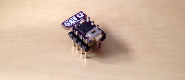
Back in the late 1970s, comedian Steve Martin had a bit about “Let’s get small!” Over on Hackaday.io, [Daniel Grießhaber], has taken that call to heart. He’s been working on DIL-Duino, a minuscule form factor Arduino in an 8-pin DIP format.

Built with an ATtiny85, the board has an area of just under 75 square millimeters (less than 8 mm x 10 mm). If you add the USB port, it still comes in at just over 144 square millimeters. [Daniel] found other small Arduino boards like the Olimexino-85s and the Nanite are not as small as his design.

The module has a QFN CPU and castellated holes around the perimeter for mounting. With pin headers, this would easily fit into a breadboard (as [Daniel] shows) or you could mount it directly to another board like a surface mount device. In fact, that’s the reason for using castellated holes: you can inspect that the solder joint at the mating SMD pad is good. You sometimes hear the technique called half-vias or leadless chip carrier.

If you note, [Daniel] used an oversized board with full holes around the perimeter and then had the board maker score the board, so the holes are cut in half. This is a better technique than trying to drill half holes on the board edge, which is difficult to do.

Naturally, this isn’t the first tiny Arduino we’ve seen. If you are an ARM fan, there’s some little bitty cards for it, too, although not quite as small as DIL-Duino.

Beautiful Weather Station Uses Acrylic, RGB LED, And And ESP8266

Everyone knows there’s form and there’s function. It isn’t fair, but people do judge on appearance, sometimes even overriding all other concerns. So while your Makerspace buddies might be impressed by your weather station built on a breadboard, your significant other probably isn’t. [Dennisv15] took an ordinary looking weather station design with a 0.96″ display and turned into an attractive desk piece with a much larger display and an artistic–and functional–enclosure.

The acrylic cloud lights up thanks to an RGB LED Neopixel strip and can indicate weather trends at a glance: red for warmer, blue for colder, flashing for inclement weather. The project was truly multidisciplinary, using a laser cutter to produce the body and the stand, a 3D-printed display bezel, and a PCB to make it easy to build.

Continue reading “Beautiful Weather Station Uses Acrylic, RGB LED, And And ESP8266”

Handy Power Supply With 3D Printed Case

You can never have too many power supplies around your workbench. It is easy to buy them or cobble something together for most purposes. But once in a while you see one that is simple and also looks good, like this one from [RegisHsu].

The project is simple since it uses off-the-shelf DC-to-DC converter modules, and good-looking LED meters to measure voltage and current. The dual supply can accept 5 to 16 V in (presumably from a wall transformer) and deliver 1.3 V to 15.5 V out at 2 amps. [RegisHsu] removed an adjustment pot from the converter board and replaced it with a 10-turn pot to allow voltage adjustment.

Given the parts, you probably don’t even need a wiring diagram. However, the part that brings it together is the 3D-printed case, which [RegisHsu] has on Thingiverse. We’ve looked at muti-turn pot replacements before, and this is hardly the first power supply project we’ve posted.

They Put The “P” In Power

Fuel cells are like batteries, sort of. Both use chemical reactions to produce electricity. The difference is that when a battery exhausts its reactants, it goes dead. In some cases, you can recharge it, but you typically get less energy back with each recharge. A fuel cell, on the other hand, will make electricity as long as you keep supplying fuel. What kind of fuel? Depends on the cell, but most often it is hydrogen or methanol.

Researchers at the University of Bath, Queen Mary University of London, and the Bristol Robotics Laboratory want to use a different fuel: urine. According to the researchers, that’s one resource we will never deplete. The fuel cell is a type of microbial fuel cell which is nothing new. The breakthrough is that the new cell is relatively inexpensive, using carbon cloth and titanium wire. Titanium isn’t usually something you think of as cheap, until you realize that conventional cells usually use platinum.

Continue reading “They Put The “P” In Power”

Pipe In (Robot) Hand

How do you make a robot hand? If you are [Robimek], you start with some plastic spiral tubing, some servo motors, and some fishing line. Oh, and you also need an old glove.

The spiral tubing (or pipe, if you prefer) is cut in a hand-like shape and fused together with adhesive. The knuckle joints are cut out to allow the tubing to flex at that point. The fishing line connects the fingertips to the servo motors.

The project uses an Arduino to drive the servos, although you could do the job with any microcontroller. Winding up the fishing line contracts the associated finger. Reeling it out lets the springy plastic pipe pull back to its original position.The glove covers the pipes and adds a realistic look to the hand.
Continue reading “Pipe In (Robot) Hand”