DrawBot Badge Represents The CNC World In Badge Design

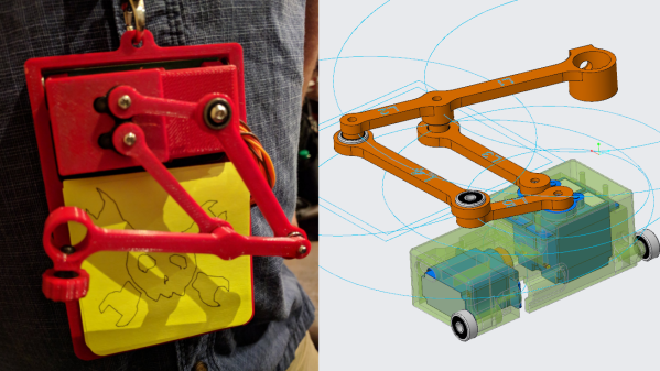
Badges come in all shapes and sizes, but a badge that draws on a stack of Post-It notes is definitely a new one. The design uses three of the smallest, cheapest hobby servos reasonably available and has a drawing quality that creator [Bart Dring] describes as “adorably wiggly”. It all started when he decided that the CNC and mechanical design world needed to be better represented in the grassroots demo scene that is the badge world, and a small drawing machine that could be cheaply made from readily available components seemed just the ticket.

Two arms control the position of a pen, and a third motor lifts the assembly in order to raise or lower the pen to the drawing surface. Gravity does most of the work for pen pressure, so the badge needs to be hanging on a lanyard or on a tabletop in order to work. An ESP32 using [Bart]’s own port of Grbl does the work of motion control, and a small stack of Post-It notes serves as a writing surface. Without the 3D printed parts, [Bart] says the bill of materials clocks in somewhere under $12.

We’ve seen similar designs doing things like writing out the time with a UV LED, but a compact DrawBot on a badge is definitely a new twist and the fact that it creates a physical drawing that can be peeled off the stack also sets it apart from others in the badgelife scene.
A Look At The Smallest Magnetic Deflection CRT Ever Made

A high-resolution LCD or OLED screen is a commodity component that we can buy on a little breakout board and plug into our microcontrollers without spending more than a dollar or two. We can buy them in sizes ranging from sub-postage-stamp to desktop TV if our budgets stretch that far, and they are easy to drive in every sense of the word. It is not so long ago though that a high-resolution LCD, even a small one, was a seriously expensive component. In consumer electronic devices such as camcorders engineers went to great lengths to avoid those costs, and [12voltvids] recently took a look at one of them.

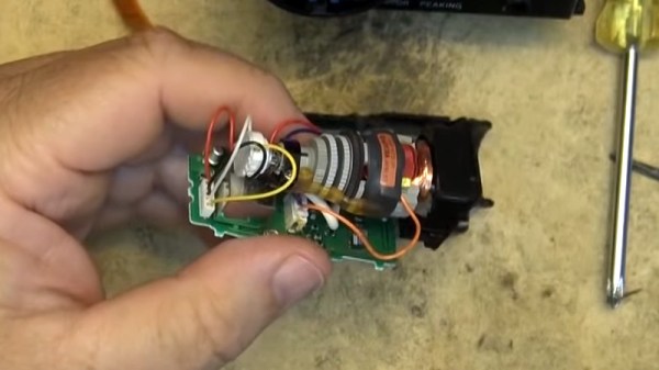
Inside the viewfinder of a miniaturized Sony camcorder is a CRT. It’s fairly mundane in the scheme of CRTs, in that it’s a monochrome device with no unexpected features. Except that is, for one thing. It’s tiny, with only a 0.5″ inch screen size. Everything else is the same as your vintage full-sized TV, it has an electron gun and a deflection and focusing coil pack, but the entire device has been miniaturized to the point at which the coil pack is larger than the screen it is driving. On the accompanying PCB are all the support circuits, including a tiny flyback transformer and a single IC –  a Rohm BA7149 electronic viewfinder driver that is as near as possible an entire CRT TV on a chip. That’s it, the whole device runs from a single 5 volt supply.

He doesn’t give the date of the camcorder, but given that it looks as though it uses 8mm cassette tapes and has a curved miniaturized design rather than the angular black exteriors that were fashionable earlier we’d guess it to be from some time around the year 2000. To give it some context, at the time one of the hottest pieces of consumer electronics would have been a Diamond Rio MP3 player, and if your desktop PC had the first of the AMD Athlon processors you probably considered it to be about the fastest you could hope to own. The surprise then is that Sony still considered it more economical even at that point to use the CRT and associated circuitry than a tiny LCD. Either way we’d agree with him that it’s a keeper, a fascinating curio for any electronics enthusiast. If we see an old camcorder going for not a lot, we’ll certainly give it a second look after this.

Continue reading “A Look At The Smallest Magnetic Deflection CRT Ever Made”

Cat Robot’s Secret To Slim Legs? Banish The Motors!

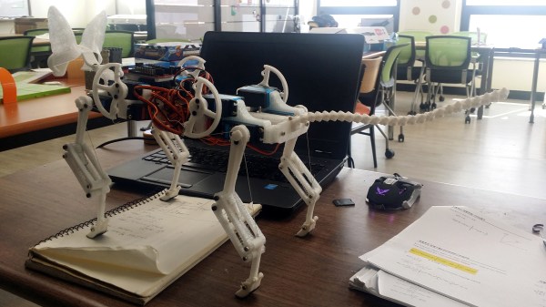
The first thing to notice about [Bijuo]’s cat-sized quadruped robot designs (link is in Korean, Google translation here) is how slim and sleek the legs are. That’s because unlike most legged robots, the limbs themselves don’t contain any motors. Instead, the motors are in the main body, with one driving a half-circle pulley while another moves the limb as a whole. Power is transferred by a cable acting as a tendon and is offset by spring tension in the joints. The result is light, slim legs that lift and move in a remarkable gait.

[Bijuo] credits the Cheetah_Cub project as their original inspiration, and names their own variation Mini Serval, on account of the ears and in keeping with the feline nomenclature. Embedded below are two videos, the first showing leg and gait detail, and the second demonstrating the robot in motion.

Continue reading “Cat Robot’s Secret To Slim Legs? Banish The Motors!”

Adding 3D Printer Power And Light Control To OctoPrint

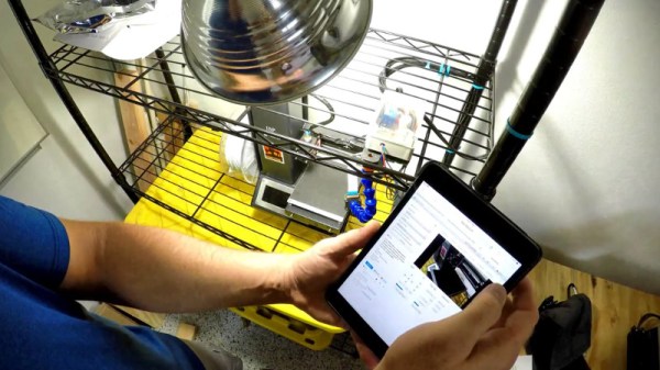
OctoPrint is a great way to monitor your printer, especially with the addition of a webcam. Using a tablet or mobile phone, you can keep an eye on what the printer is doing from anywhere in the house (or world, if you take the proper precautions), saving you from having to sit with the printer as if it’s an infant. But simply watching your printer do its thing is only a small slice of the functionality offered by OctoPrint’s vast plugin community.

As [Jeremy S Cook] demonstrates, it’s fairly easy to add power control for the printer and auxiliary lighting to your OctoPrint setup. Being able to flick the lights on over the print bed is obviously a big help when monitoring it via webcam, and the ability to turn the printer off can provide some peace of mind after the print has completed. If you’re particularly brave it also means you could power on the printer and start a print completely remotely, but good luck if that first layer doesn’t go down perfectly.

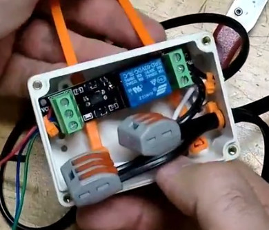
In terms of hardware, you only need some 3.3V relays for the Raspberry Pi running OctoPrint to trigger, and an enclosure to put the wiring in. [Jeremy] uses only one relay in this setup to power the printer and lights at once, but with some adjustment to the software, you could get independent control if that’s something you’re after.

On the software side [Jeremy] is using an OctoPrint plugin called “PSU Control”, which is actually intended for controlling an ATX PSU from the Pi’s GPIO pins, but the principle is close enough to throw a relay. Other plugins exist which allow for controlling a wider away of devices and GPIO pins if you want to make a fully remote controlled enclosure. Plus you can always whip up your own OctoPrint plugin if you don’t find anything that quite meets your switching needs.

[Jeremy] previously documented his unique mount to keep his Raspberry Pi and camera pointed at his printer, which is naturally important if you want to create some cool videos with Octolapse.

Continue reading “Adding 3D Printer Power And Light Control To OctoPrint”

The Tiny, Pocket-Sized Robot Meant For Hacking

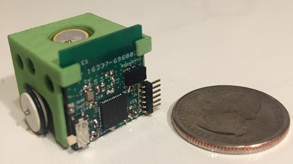
The world is full of educational robots for STEAM education, but we haven’t seen one as small or as cute as the Skoobot, an entry in this year’s Hackaday Prize. It’s barely bigger than an inch cubed, but it’s still packed with motors, a battery, sensors, and a microcontroller powerful enough to become a pocket-sized sumo robot.

The hardware inside each Skoobot is small, but powerful. The main microcontroller is a Nordic nRF52832, giving this robot an ARM Cortex-M4F brain and Bluetooth. The sensors include a VL6180X time of flight sensor that has a range of about 100mm. Skoobot also includes a light sensor for all your robotic photovoring needs. Other than that, the Skoobot is just about what you would expect, with a serial port, a buzzer, and some tiny wheels mounted in a plastic frame.

The idea behind the Skoobot is to bring robotics to the classroom, introducing kids to fighting/sumo robots, while still being small, cheap, and cute. To that end, the Skoobot is completely controllable via Bluetooth so anyone with a phone, a Pi, or any other hardware can make this robot move, turn, chase after light, or sync multiple Skoobots together for a choreographed dance.

While the Skoobot is an entry for this year’s Hackaday Prize, the creator of the Skoobot, [Bill Weiler] is also making these available on Crowd Supply.

Camera Uses Algorithms Instead Of Lenses

A normal camera uses a lens to bend light so that it hits a sensor. A pinhole camera doesn’t have a lens, but the tiny hole serves the same function. Now two researchers from the University of Utah. have used software to recreate images from scattered unfocused light. The quality isn’t great, but there’s no lens — not even a pinhole — involved. You can see a video, below.

The camera has a sensor on the edge of a piece of a transparent window. The images could resolve .1 line-pairs/mm at a distance of 150 mm and had a depth of field of about 10 mm. This may seem like a solution that needs a problem, but think about the applications where a camera could see through a windshield or a pair of glasses without having a conventional camera in the way.

Continue reading “Camera Uses Algorithms Instead Of Lenses”

String Art Robot Is An Autorouter In Reverse

In the depths of Etsy and Pinterest is a fascinating, if tedious, artform. String art, the process of nailing pins in a board and wrapping thread around the perimeter to create shapes and shading, The most popular project in this vein is something like putting the outline of a heart, in string, in the shape of your home state. Something like that, at least.

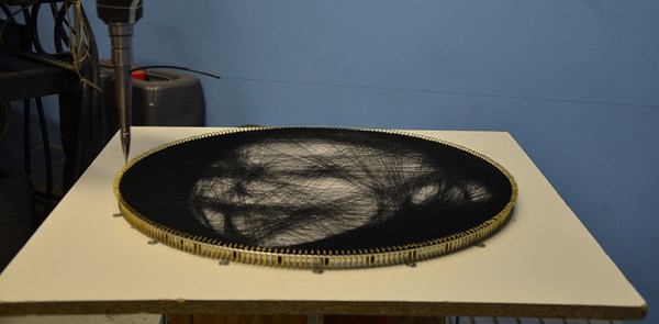
While this artform involves about as much effort as pallet wood furniture, there is an interesting computational aspect of it: you can create images with string art, and doing this is a very, very hard problem to solve with an algorithm. Researchers at TU Wien have brought out the best that string art has to offer. They’ve programmed an industrial robot to create portraits out of string.

The experimental setup for this is about as simple as it gets. It’s a circular frame studded with 256 hooks around the perimeter. An industrial robot arm takes a few kilometers of thread winds a piece of string around one of these hooks, then travels to another hook. Repeat that thousands and thousands of times, and you get a portrait of Ada Lovelace or Albert Einstein.

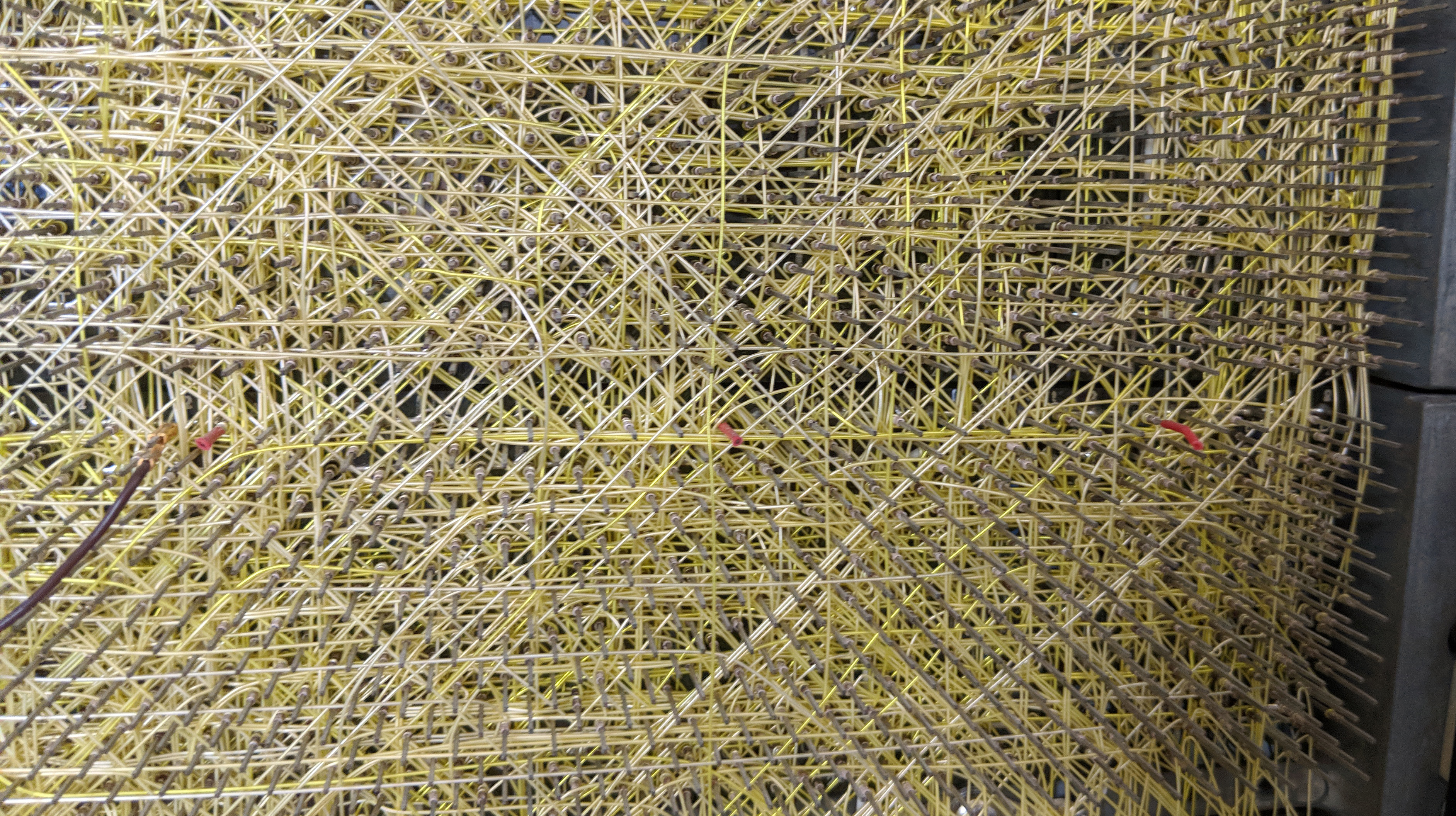
The wire wrapped backplane of a DEC PDP-11. This was assembled by a robot that was programmed with an autorouter. It’s also string art.

The real trick here is the algorithm that takes an image and translates it into the paths the string will take. This is an NP-hard problem, but it is a surprisingly well-studied problem. The first autorouters — the things you should never trust to route traces between the packages on your PCB — we created for wire wrapped computers. Here, computers would find the shortest path between whatever pins had to be connected together. There were, of course, limitations: pins could only have so many connections on them thanks to the nature of wire wrapping, and you couldn’t have one gigantic mass of wires for a parallel bus. The first autorouters were string art algorithms, only in reverse.

You can take a look at the complete publication here.

You’ll also find prior art (tee-hee) in our own pages. Here is an artist doing it by hand, and here’s a machine to do it for you if you’re lazy. We’ve even seen further work on the underlying algorithm on Hackaday.io.