Hackers love random numbers, or more accurately, the pursuit of them. It turns out that computers are so good at following our exacting instructions that they are largely incapable of doing anything that would fit the strict definition of randomness — which has lead to some elaborate methods of generating the unexpected.
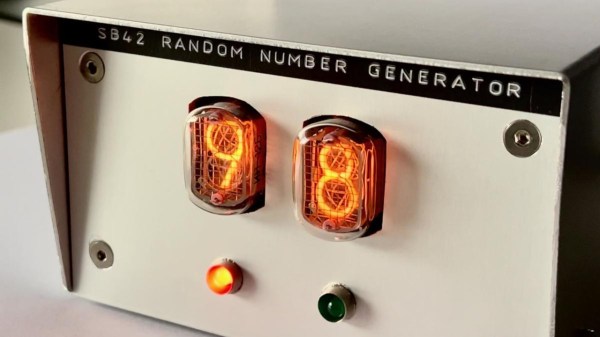
Admittedly, the SB42 Random Number Generator built by [Simon Boak] isn’t exactly something you’d be using for cryptography. The method used to generate the digits, a pair of 555 timers sending pulses through linear-feedback shift registers, would at best be considered pseudo-random. Plus the only way of getting the digits out of the machine is by extracting them from the Nixie tubes with your Mark I Eyeballs. But it absolutely excels at the secondary reason many hackers like to build their own randomness rigs — it looks awesome.
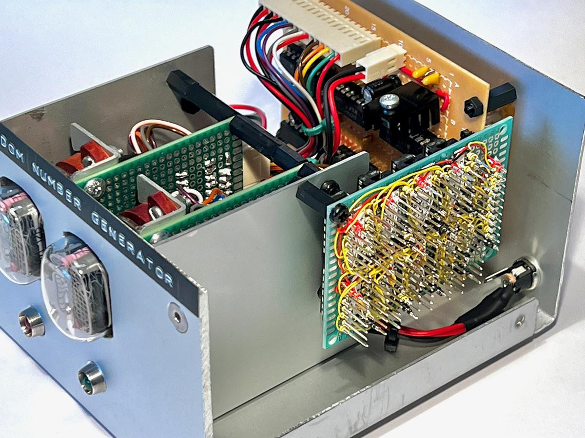 Externally, it absolutely nails the look of a piece of vintage DIY year. Down to the classic white-on-black label tape. But open up the hood, and you’re treated to a real rarity these days: wirewrap construction. In an era where you can get PCBs made and shipped to your door for literally pennies, [Simon] is out there keeping the old ways alive. It doesn’t just look the part either. Unlike most modern projects we see, there isn’t a multi-core microcontroller behind the scenes doing all the work, it’s logic gates all the way down.
This isn’t the first random-ish number generator that we’ve seen use shift registers. But if you’re looking for something that might actually pass some randomness checks, and don’t mind working with something a bit spicy, you could check out some of the previous devices we’ve covered that used radioactive decay as an entropy source.
Continue reading “Random Number Generator Is A Blast From The Past”