If you’re anything like us you’ve been keeping a close eye on the development of RISC-V: an open standard instruction set architecture (ISA) that’s been threatening to change the computing status quo for what seems like forever. From its humble beginnings as a teaching tool in Berkeley’s Parallel Computing Lab in 2010, it’s popped up in various development boards and gadgets from time to time. It even showed up in the 2019 Hackaday Supercon badge, albeit in FPGA form. But getting your hands on an actual RISC-V computer has been another story entirely. Until now, that is.
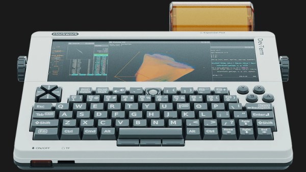
Clockwork has recently announced the availability of the DevTerm R-01, a variant of their existing portable computer that’s powered by a RISC-V module rather than the ARM chips featured in the earlier A04 and A06 models. Interestingly the newest member of the family is actually the cheapest at $239 USD, though it’s worth mentioning that not only does this new model only include 1 GB of RAM, but the product page makes it clear that the RISC-V version is intended for experienced penguin wranglers who aren’t afraid of the occasional bug.

Beyond the RISC-V CPU and slimmed down main memory, this is the same DevTerm that our very own [Donald Papp] reviewed earlier this month. Thanks to the modular nature of the portable machine, this sort of component swapping is a breeze, though frankly we’re impressed that the Clockwork team is willing to go out on such a limb this early in the product’s life. In our first look at the device we figured at best they would release an updated CPU board to accommodate the Raspberry Pi 4 Compute Module, but supporting a whole new architecture is a considerably bolder move. One wonders that other plans they may have for the retro-futuristic machine. Perhaps a low-power x86 chip isn’t out of the question?