DIY Machine Enables PEMF Therapy On A Budget

We’re certainly not qualified to say whether or not pulsed electromagnetic field (PEMF) therapy will actually reduce your stress or improve your circulation, but there seems to be enough legitimate research going on out there that it might be worth a shot. After all, unless you’ve got a pacemaker or other medical implant, it seems pretty unlikely a magnetic field is going to make anything worse. Unfortunately commercial PEMF machines can cost thousands of dollars, making it a fairly expensive gamble.

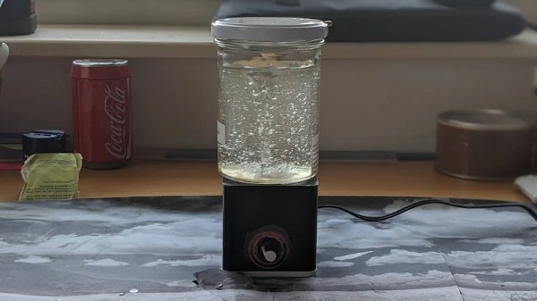
But what if you could build one for as little as $10 USD? That’s the idea behind the simple DIY PEMF machine [mircemk] has been working on, and judging by its ability to launch bits of metal in the video below, we’re pretty confident it’s indeed producing a fairly powerful electromagnetic field. Even if it doesn’t cure what ails you, it should make an interesting conversation piece around the hackerspace.

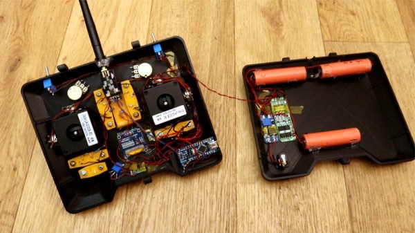
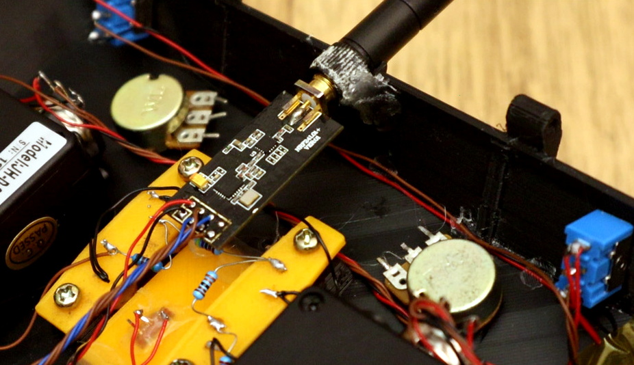
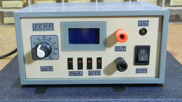
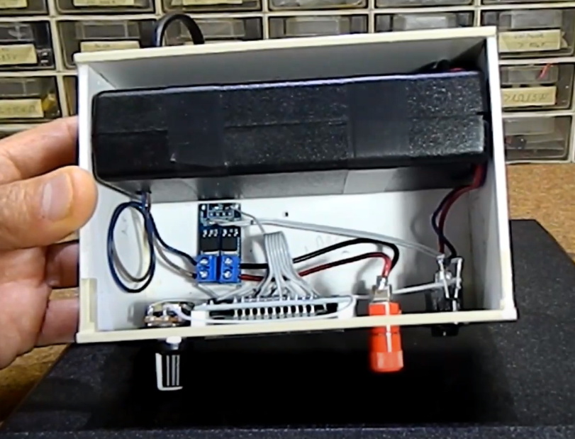
While the outside of the machine might look a bit imposing, the internals really are exceptionally straightforward. There’s an old laptop power supply providing 19 VDC, a dual-MOSFET board, a potentiometer, and a simple signal generator. The pulses from the signal generator trip the MOSFET, which in turn dumps the output of the laptop power supply into a user-wound coil. [mircemk] has a 17 cm (6.7 inch) open air version wrapped with 200 turns of copper wire used for treating wide areas, and an 8 cm (3 inch) diameter version with 300 windings for when you need more targeted energy.

Some skepticism is always in order with these sort of medicinal claims, but commercial PEMF machines do get prescribed to users to help promote bone growth and healing, so the concept itself is perhaps not as outlandish as it might seem.

Continue reading “DIY Machine Enables PEMF Therapy On A Budget”

Active Suspension On A DIY Racing Car

In automotive engineering, almost every design choice is a trade-off, like performance versus fuel economy, straight-line speed versus cornering, or strength versus weight. Inspired by controversial technology for the 2020 Formula 1 season, [Wesley Kagan] is fitting his DIY racing car with actuators to change the suspension geometry while driving.

The controversial technology in question is Mercedes’ DAS (Dual Axis Steering). By pushing the steering wheel in and out, the driver and change the wheel alignment to toe-out (wheels pointing outwards) for better cornering stability, or neutral for the straight sections.

Like many racing cars, [Wesley] used A-arm suspension on his racing car. By replacing the top arms with telescoping tubes with mounted actuators, the geometry can be actively adjusted. For this proof of concept, he used linear actuators but plans to move to a hydraulic system for improved speed and force. The length of the A-arms is sensed with ultrasonic sensors, while a potentiometer senses the suspension position.

Tuning the software for optimum performance will probably require some track testing which we hope to see in the future. This is not the first time [Wesley] has taken inspiration from a multimillion-dollar project and implemented it in his garage. Just check out how he converted a Miata and a Harbor Freight engine to a Free Valve system.

Continue reading “Active Suspension On A DIY Racing Car”

An Easy DIY Pedal Set For Racing Sims

The racing sim scene has always had a strong DIY subculture, as enthusiasts seeking the most realistic-feeling peripherals set out to modify off-the-shelf offerings for greater authenticity. Others go further and craft their own builds from the ground up. [ilge] has done just that, putting together his own set of pedals for sim racing.

The build relies primarily on 3D printed components, with a few springs and some nuts and bolts to hold everything together. Gear teeth on the pedal arms interface with matching gears mounted on potentiometers. These are then wired into an Arduino Pro Micro, which reads the individual pots via analog inputs and then acts as a USB Human Interface Device to the computer.

[ilge] tests the setup with a variety of games, including the popular Euro Truck Simulator and iRacing. It’s a great cheap way to get started with a pedal set for a sim rig. From here, the sky really is the limit; we’d love to see an upgraded version with a load-cell on the brake for better pedal feel. We’d be surprised if an H-shifter isn’t in the works, too. Video after the break.

Continue reading “An Easy DIY Pedal Set For Racing Sims”

A 3D Printed Magnetic Stirrer For Your DIY Chemistry Projects

When mixing or agitating delicate solutions in the chemistry lab, a magnetic stirrer is often the tool of choice. They’re able to be easily sterilized and cleaned, while maintaining isolation between the mechanical parts and the solutions in question. While they can be purchased off the shelf, [Max Siebenschläfer] whipped up a design that can easily be built at home.

The build consists of a 3D printed base, containing a simple brushed motor. This is hooked up to a motor controller fitted with a simple potentiometer for adjusting the speed of rotation. The motor is then fitted with a small 3D printed spinner containing two magnets. A similar 3D printed part acts as a stirrer, and is fitted with a matching pair of magnets, and dropped into the solution. The magnets in the stirrer are attracted to the ones on the end of the motor, and so when the motor spins, the stirrer spins in the solution, with no physical contact required.

It’s a simple way to build a magnetic stirrer at home without having to shell out big money for a laboratory grade unit. We imagine this could be put to fun use for stirring coffee or cocktails, too – if built with a food-grade spinner. More advanced designs are also possible for the eager home scientist. Video after the break.

Continue reading “A 3D Printed Magnetic Stirrer For Your DIY Chemistry Projects”

DIY Ribbon Controller For A DIY Synth

There’s kind of a special joy in making instruments, no matter how simple or complex they are. Even if it’s a straight-up noisemaker, that’s noise you can be proud of. And besides, noise plus rhythm equals music.

Whenever you’re ready to have some next-level fun, try making controllers for your DIY instruments. Synthesizers of all stripes are often controlled with various types of potentiometers. While it would definitely be an interesting exercise to make your own standard twist-style potentiometer, [lonesoulsurfer] shows that making a ribbon controller is relatively easy.

A ribbon controller is essentially a deconstructed potentiometer that uses your finger to actuate the wiper. Here the wiper is made from Velostat, a fun, low-cost conductive material that’s also pressure-sensitive. The rest of the ribbon controller is a sandwich of thin copper plates and non-conductive plastic mounted on a wood base.

But what’s a fun controller without a fun instrument to control? As a special bonus, [lonesoulsurfer] made a little square wave-squirting synth based on the 4046 hex inverter and included the schematic for it. Slide your finger past the break to check ’em both out.

Depending on what you have lying around, it may be easier to make analog instruments like this rubber band boinger or its country cousin, the wheelbarrow bass.

Continue reading “DIY Ribbon Controller For A DIY Synth”

Better Simulators With Homemade Potentiometers

Perhaps you’ve played a flight simulator before, using something like a mouse and keyboard. That’s a fine experience, but like any other activity you can get a lot more out of it if you put a little more effort into the experience. Some will upgrade to a joystick for a modest improvement, and others will build incredible accurate cockpit replicas down to the smallest detail. The builders of these “pits” are always looking for ways of improving their setups, and it’s from this world that we find a method of building specialized, inexpensive hall-effect sensors.

A hall-effect sensor is a circuit that outputs a voltage based on the presence of an external magnetic field. These can be used to make compasses, but with a permanent magnet in close proximity can also be used to create a potentiometer-like device at lower cost and with higher precision than a similarly-priced pot. There was a method of building these in the simulator world using the housing of a Bic pen and some strong glue, but [LocNar] has improved on this method as well. He repurposed some bearings and some stock metal tubing in order to fabricate a professional-level sensor at a fraction of the cost.

This build is essentially a solution for anyone needing a potentiometer that’s easier to build, less expensive, has higher precision, and interacts with a digital input in a much more predictable (and programmable) way. Certainly this has applications in the simulator world, but will work for many other applications. If you’ve never thought about the intricacies (and shortcomings) of potentiometers, some other folks have taken a deep dive into that as well.

Thanks to [Keith O] for the tip!

DIY Six Channel Arduino RC Transmitter

It’s wasn’t so long ago that RC transmitters, at least ones worth owning, were expensive pieces of gear. Even more recently than that, the idea of an RC transmitter running an open source firmware would have been considered a pipe dream. Yet today buying cheap imported transmitters and flashing a community developed firmware (if it didn’t come with it pre-installed to begin with) is common place. It’s not much of a stretch to say we’re currently in the “Golden Age” of hobby RC transmitters.

But what if even cheap hardware running customizable software isn’t enough? What if you want to take it to the next level? In that case, [Electronoobs] has an Arduino powered RC transmitter with your name on it. But this is no scrap of protoboard with a couple of cheap joysticks on it, though he has made one of those too. The goal of this build was for it to look and perform as professional as possible while remaining within the hobbyist’s capabilities. The final product probably won’t be winning any design awards, but it’s still an impressive demonstration of what the individual hacker and maker can pull off today with the incredible technology we have access to.

So what goes into this homebrew radio control system? Inside the back panel [Electronoobs] mounted the batteries, charging module, and the voltage regulator which steps the battery voltage down to the 3.3 V required to drive the rest of the transmitter’s electronics. On the flip side there’s an Arduino Nano, an NRF24 module, and an OLED display. Finally we have an assortment of switches, buttons, potentiometers, and two very nice looking JH-D202X-R2 joysticks for user input.

As you might have guessed, building your own transmitter means building your own receiver as well. Unfortunately you won’t be able to bind your existing RC vehicles to this radio, but since the receiver side is no more complicated than another Arduino Nano and NRF24 module, it shouldn’t be hard to adapt them if you were so inclined.

Low-cost consumer RC transmitters can be something of a mixed bag. There are some surprisingly decent options out there, but it’s not a huge surprise that hackers are interested in just spinning up their own versions either.
Continue reading “DIY Six Channel Arduino RC Transmitter”