Custom Caliper Tracks For When You’re Going The Distance

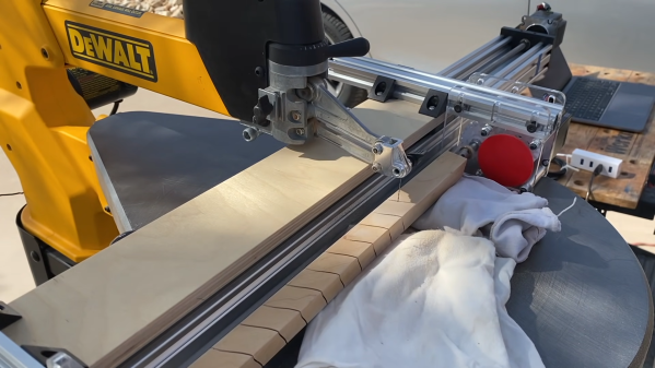
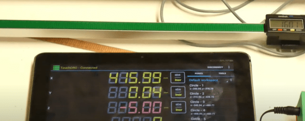
The working principle of digital calipers is mysterious enough that we’d never think to dismantle, much less improve them, right? Well, think again, as [Limi DIY] retrofits the processing element onto a custom track, extending the calipers measurement distance to a whopping 650 mm. Combined with a prior project to extract the measurement data, the result makes for a working multi-axis digital readout, a handy device for machine tools like a manual lathe or milling machine.

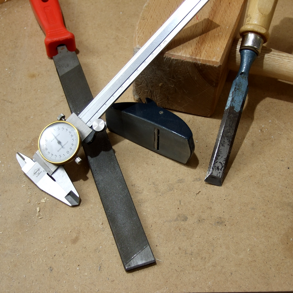
Digital calipers operate on the principle of measuring an array of variable capacitors. If we scratch our heads and look back at our physics notes, we’ll recall that the capacitance between two parallel conductive plates is linearly proportional to the surface area. By fixing one dimension of both plates and by sliding one plate over the other, we effectively change the area, giving ourselves a simple linear displacement sensor! (There are some classy error-correcting techniques too, and this [PDF] is a great place to look for more details.)

The theory takeaway is that this array of parallel plates can be embedded directly into a printed circuit board. We just need to know the dimensions. After some close measurement work, [Limi DIY] extracted the crucial measurements and fabbed a PCB with the pattern duplicated over 650 mm. After retrofitting the original processing element onto this new track, they had a working measurement device that’s far longer than the original!

If you’ve ever been tempted to disassemble your calipers but too nervous to bite off the investment, now’s your chance to follow along as [Lima DIY] demonstrates the gratuitous disassembly process for you in video format. And the fruits of their labor is also captured on a project post that includes the key dimensions if you’re looking to do the same thing.

If you’re looking for other ways to improve your calipers, why not start by giving them a major battery life boost.

Thanks to [absd] via [Jubilee Discord] for the tip!

Continue reading “Custom Caliper Tracks For When You’re Going The Distance”

Better Mousetraps (or Screw Drives) Don’t Always Win

I’ve noticed, lately, that slotted screw heads are all but gone on new equipment. The only thing that I find remarkable about that is that it took so long. While it is true that slotted heads have been around for ages, better systems are both common and have been around for at least a century.

Check out those cool threads.

The reason slotted heads — technically known as the drive — are so common is probably because they are very easy to make. A hacksaw is sufficient for the job and there are other ways to get there, too. The only advantages I know of for the user is that you can easily clean a slotted drive and — possibly — use field expedient items like butter knives and quarters to turn the screw. I’ve heard people claim that it also is a feature that the screwdriver can pry things like paint can lids, but that’s a feature of the tool, not the screw drive.

The disadvantages, though, are significant. It is very hard to apply lots of torque to a slotted screw drive without camming it out or snapping the head off the screw. The screwdriver isn’t self-centering either, so applying force off-axis is common and contributes to the problem.

Continue reading “Better Mousetraps (or Screw Drives) Don’t Always Win”

How To Get Into Cars: Land Speed Racing

Land speed racing is one of the oldest forms of motorsport, and quite literally consists of going very, very fast in (ideally) a straight line. The higher the speed your car can attain, the better! It’s about the pure pursuit of top speed above all else, and building a car to compete is a calling for a dedicated few. If you’d like to join them, here’s how to go about it.

Faster, Faster, Faster!

A great example of the “36HP” Volkswagen class, which challenges competitors to set land speed records using only classic VW engines, with categories for various levels of modification. Note the aero wheels and raked stance. Credit: Utah Salt Flats Racing Association

While taking the outright land speed record typically requires a jet-engined sled of singular design, there is plenty of land speed competition to be had in various classes for competitors fielding their own entries. There are vintage classes for older technology engines, still popular from the dawn of hotrodding, like Ford Flathead V8s and other contemporary motors. There are also classes split by engine displacement, number of cylinders, aerodynamic modifications, or the type of fuel used.

Racers often pick a record or set of records they wish to beat – for example, wanting to set the the fastest speed for a gasoline-powered, naturally-aspirated four cylinder – and build their car to that end. Alternatively, a racer might build a car with a large V8 engine, for example, to compete in one class, and then disable several cylinders on a later run to try and snatch records in lower classes as well. Continue reading “How To Get Into Cars: Land Speed Racing”

CNC Scroll Saw Add-On Cuts Beautiful Wooden Spirals

If there’s one thing that woodworkers have always been good at, it’s coming up with clever jigs and work-holding solutions. Most jigs, however, are considerably simpler and more static than this CNC-controlled scroll saw add-on that makes cool wooden spirals a snap.

As interesting as the products of this setup are, what we like about this is the obvious care and craftsmanship [rschoenm] put into making what amounts to a hybrid between a scroll saw and a lathe. Scroll saws are normally used to make narrow-kerf cuts in thin, delicate materials, often with complicated designs using very tight radius turns. In this case, though, stock is held between centers on the lathe-like carriage. The jig uses a linear slide driven by a stepper and a lead screw to translate the workpiece perpendicular to the scroll saw blade while a geared headstock rotates it. Starting with the blade inserted into a through-hole, the saw slowly cuts a beautiful nested spiral down the length of the workpiece. An Uno, a GRBL shield, and some stepper drivers let a little G-code control the two axes of the jig.

The video below shows it in action; things do get a bit wobbly as the cut progresses, but in general the jig works wonderfully and results in some lovely pieces. At first we thought these would purely be objets d’art, but then we thought about this compression screw grinder for DIY injection molding machines and realized these wooden screws look pretty similar.

Continue reading “CNC Scroll Saw Add-On Cuts Beautiful Wooden Spirals”

3D Printed Vortex Cooled Rocket Needs To Stop Leaking

Rocket engines are known for one thing above all else, and that’s getting hot. It’s this very property that makes them such a challenge to build and run from a materials engineering standpoint. It’s hard enough to build one with advanced metal alloys, but [Integza] presses on with trying to make one on a 3D printer. Progress is being made, but success remains elusive.  (Video, embedded below.)

To try and mitigate the thermal effects of burning propellants in his engine design, [Integza] looked to vortex cooling. This is where oxygen is swirled around the outer edge of the combustion chamber in a vortex, acting as a buffer layer between the burning fuel and the chamber walls. With 3D printed chamber components, keeping temperatures as low as possible is key, after all. Unfortunately, despite using a special ceramic-laden resin for printing and lathering the rocket components in various refractory materials, it wasn’t possible to stop the chambers leaking. Solid combustion was possible for a few seconds at a time, but eventually each motor tested turned into a ball of flames as the walls broke down.

Thankfully, nobody was hurt in testing, and [Integza] has a clear idea of the problems that need to be fixed in the next iteration. We’ve featured other vortex cooled rockets before – the theory is sound. As always, the devil is in the implementation.

Continue reading “3D Printed Vortex Cooled Rocket Needs To Stop Leaking”

Machinist’s Accuracy Vs. Woodworker’s Precision

There are at least two ways of making parts that fit together exactly. The first way is the Cartesian way, and the machinists way. Imagine that you could specify the size of both the hole and the peg that you’d like to put into it. Just make sure your tolerances are tight enough, and call out a slightly wider hole. Heck, you can look up the type of fit you’d like in a table, and just specify that. The rest is a simple matter of machining the parts accurately to the right tolerances, and you’re done.

The machinist’s approach lives and dies on that last step — making the parts accurately fit the measure. Contrast the traditional woodworker’s method, or at least as it was taught to me, of just making the parts fit each other in the first place. This is the empirical way, the Aristotelian way if you will. You don’t really have to care if the two parts are exactly 30.000 mm wide, as long as they’re precisely the same length. And woodworkers have all sorts of clever tricks to make things the same, or make them fit, without measuring at all. Their methods are heavy on the jigs and the clever set-ups, and extraordinarily light on the calipers. To me, coming from a “measure carefully, and cut everything to measure” background, these ways of working were a revelation.

This ends up expressing perfectly the distinction between accuracy and precision. Sometimes you need to hit the numbers right on, and other times, you just need to get the parts to fit. And it’s useful to know which of these situations you’re actually in.

Of course, none of this is exclusive to metal or wood, and I’m actually mentioning it because I find myself using ideas that I learned in one context and applying them in the other. For instance, if you need sets of holes that match each other perfectly, whether in metal or wood, you get that precision for free by drilling through two sheets at one time, or by making a template — no measuring needed. Instead of measuring an exact distance from a feature, if all you care about is two offsets being the same, you can find a block of scrap with just about the right width, and use that to mark both distances. Is it exactly 1.000″ wide? Nope. But can you use this to mark identical locations? Yup.

You can make surprisingly round objects in wood by starting with a square, and then precisely marking the centers of the straight faces, and then cutting off the corners to get an octagon. Repeat with the centers and cutting until you can’t see the facets any more. Then hit it with sandpaper and you’re set. While this won’t make as controlled a diameter as would come off a metal lathe, you’d be surprised how well this works for making round sheet-aluminum circles when you don’t care so much about the diameter. And the file is really nothing other than the machinist’s sandpaper (or chisel?).

I’m not advocating one way of working over the other, but recognizing that there are two mindsets, and taking advantage of both. There’s a certain freedom that comes from the machinist’s method: if both parts are exactly 25.4 mm long, they’re both an accurate inch, and they’ll match each other. But if all you care about is precise matching, put them in the vise and cut them at the same time. Why do you bother with the calipers at all? Cut out the middle-man!

Motor Controller Reverse Engineering Releases Smoke

It may have been designed for a sewing machine, but [Haris Andrianakis] found his imported DC brushed motor was more than up to the challenge of powering his mini lathe. Of course there’s always room for improvement, so he set out to reverse engineer the motor’s controller to implement a few tweaks he had in mind. Unfortunately, things took an unexpected turn when plugging his AVR programmer into the board’s ISP socket not only released the dreaded Magic Smoke, but actually tripped the breaker and plunged his bench into darkness.

Studying how the Hall-effect sensors in the motor are wired.

Upon closer inspection, it turned out the board has no isolation between the high voltage side and its digital logic. When [Haris] connected his computer to it via the programmer, the 330 VDC coming from the controller’s rectifier shorted through the USB bus and tripped the Earth-leakage circuit breaker (ELCB). The good news is that his computer survived the ordeal, and even the board itself seemed intact. But the shock must have been too much for the microcontroller he was attempting to interface with, as the controller no longer functioned.

Now fully committed, [Haris] started mapping out the rest of the controller section by section. In the write-up on his blog, he visually masks off the various areas of the PCB so readers have an easier time following along and understanding how the schematics relate to the physical board. It’s a nice touch, and a trick worth keeping in mind during your own reverse engineering adventures.

In the end, [Haris] seems to have a good handle on what the majority of the components are up to on the board. Which is good, since getting it working again now means replacing the MCU and writing new firmware from scratch. Or perhaps he’ll just take the lessons learned from this controller and spin up his own custom hardware. In either event, we’ll be keeping an eye out for his next post on the subject.