Disgusting Apple II Monitors Live Again

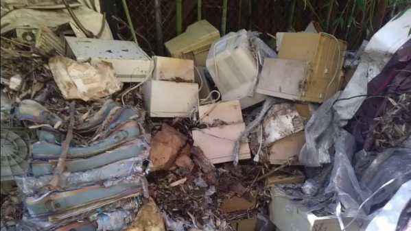
[The 8-Bit Guy] recently went to check out a stash of old Apple II Color monitors which had been sitting outside in a trash pile for 20 years, and decided to bring one home to restore. As you can see from the lead photo, they were dirty — really dirty. Surprisingly, the team of volunteers who discovered these monitors had fired them up, and every one of them works to some extent or another.

Check out the video below as he cleans up this filthy monitor and starts troubleshooting. You’ll chuckle aloud when he turns the circuit board over to desolder a mysterious diode, and when he flips the board back over, the diode has disappeared (it actually disintegrated into dust on his lab bench). For the curious, one commenter on YouTube found that it was a glass passivated and encapsulated fast recovery diode called a V19. There’s going to be a part 2, and we have every confidence that [The 8-Bit Guy] will succeed and soon add a shiny, like-new monitor to his collection.

If you’re a collector of old monitors, this demonstrates that they can survive quite a bit of abuse and exposure. We’re not sure that rummaging through your local landfill is the best idea, but if you run into an old monitor that has been exposed to the elements, don’t be so quick to dismiss it as a lost cause. Do you have any gems that you’ve restored from the trash? Let us know in the comments.

Continue reading “Disgusting Apple II Monitors Live Again”

Telemetry Debate Rocks Audacity Community In Open Source Dustup

Starting an open source project is easy: write some code, pick a compatible license, and push it up to GitHub. Extra points awarded if you came up with a clever logo and remembered to actually document what the project is supposed to do. But maintaining a large open source project and keeping its community happy while continuing to evolve and stay on the cutting edge is another story entirely.

Just ask the maintainers of Audacity. The GPLv2 licensed multi-platform audio editor has been providing a powerful and easy to use set of tools for amateurs and professionals alike since 1999, and is used daily by…well, it’s hard to say. Millions, tens of millions? Nobody really knows how many people are using this particular tool and on what platforms, so it’s not hard to see why a pull request was recently proposed which would bake analytics into the software in an effort to start answering some of these core questions.

Now, the sort of folks who believe that software should be free as in speech tend to be a prickly bunch. They hold privacy in high regard, and any talk of monitoring their activity is always going to be met with strong resistance. Sure enough, the comments for this particular pull request went south quickly. The accusations started flying, and it didn’t take long before the F-word started getting bandied around: fork. If Audacity was going to start snooping on its users, they argued, then it was time to take the source and spin it off into a new project free of such monitoring.

The situation may sound dire, but truth be told, it’s a common enough occurrence in the world of free and open source software (FOSS) development. You’d be hard pressed to find any large FOSS project that hasn’t been threatened with a fork or two when a subset of its users didn’t like the direction they felt things were moving in, and arguably, that’s exactly how the system is supposed to work. Under normal circumstances, you could just chalk this one up to Raymond’s Bazaar at work.

But this time, things were a bit more complicated. Proposing such large and sweeping changes with no warning showed a troubling lack of transparency, and some of the decisions on how to implement this new telemetry system were downright concerning. Combined with the fact that the pull request was made just days after it was announced that Audacity was to be brought under new management, there was plenty of reason to sound the alarm.

Continue reading “Telemetry Debate Rocks Audacity Community In Open Source Dustup”

Projecting Moving Images In Air With Lasers

You’ve seen it a million times in science fiction movies and TV shows: a moving holographic display. From Princess Leia asking for help to virtual tennis on Total Recall, it is a common enough idea. [Dan Smalley]’s team at BYU has made progress in projecting moving 3D images in thin air. While they might not be movie quality, they are a start, and, after all, you have to start somewhere.

The display traps a small particle in the air with a laser beam and then moves that particle around, leaving behind an illuminated path in the air. You can see the effect in the video below. The full paper explains how a type of ray tracing allows the relatively small optical trap display to appear larger and more fluid. While it does make images seem to appear behind the display’s actual volume, it also requires eye tracking to work since the illusion only works from a certain perspective.

These are not, of course, technically holograms. That’s actually an advantage in some cases because holograms require a tremendous amount of data that increases rapidly as the size of a display scales up. The optical trap display uses a much more manageable data rate.

We’ve seen optical trap displays before. In fact, volumetric displays seem to be all the rage lately.

Continue reading “Projecting Moving Images In Air With Lasers”

Gassing Up: Understanding The Liquid Fuel Distribution Network

When someone talks about “The Grid,” as in “dropping off the grid” or “the grid is down,” we tend to think in terms of the electromagnetic aspects of the infrastructure of modern life. The mind’s eye sees The Grid as the network of wires that moves electricity from power plants to homes and businesses, or the wires, optical cables, and wireless links that form the web of data lines that have stitched the world together informatically.

The Grid isn’t just about power and data, though. A huge portion of the infrastructure of the developed world is devoted to the simple but vital task of moving liquid fuels from one place to another as efficiently and safely as possible. This fuel distribution network, comprised of pipelines, railways, and tanker trucks, is very much part of The Grid, even if it goes largely unseen and unnoticed. At least until something major happens to shift attention to it, like the recent Colonial Pipeline cyberattack.

Continue reading “Gassing Up: Understanding The Liquid Fuel Distribution Network”

Soil Moisture Sensors, How Do They Work?

In a way, the magic of a soil moisture sensor’s functionality boils down to a simple RC circuit. But of course, in practice there is a bit more to it than that. [rbaron] explains exactly how capacitive soil moisture sensors work simply, clearly, and concisely. He also shows, with a short video, exactly how their output changes in response to their environment, and explains how it informed his own sensor design.

At its heart, a moisture sensor measures how quickly (or slowly) a capacitor charges through a resistor, but in these sensors the capacitor is not a literal component, but is formed by two PCB traces that are near one another. Their capacitance — and therefore their charging rate — changes in response to how much water is around them. By measuring this effect on a probe sunk into dirt, the sensor can therefore indirectly measure the amount of water in the soil.

This ties into his own work on b-parasite: an open-source, all-in-one wireless soil moisture sensor (which was also a runner-up in our Earth Day contest) that broadcasts over BLE and even includes temperature readings. One thing to be mindful of if you are making your own PCBs or ordering them from a fab house is that passing current through metal in a moist environment is a recipe for oxidation, so it’s important not to expose bare traces to wet soil. A good coated PCB should avoid this problem, but one alternative we have seen proposed is to use graphite rods in place of metal.

Actively Balancing A Robot With A Gyroscope

Self-balancing robots are a common hacker project, but we don’t often see them using spinning gyroscopes to achieve that balance. Robot master [James Bruton] decided to build a robotic platform with active gyroscopic stabilization, starting from a simple proof of concept.

A gyroscope can balance, but cannot actively counteract external forces directly. However, if the gyroscope is tilted around an axis it will exert a force perpendicular to that axis of tilt, known as gyroscopic precession. By tilting the gyroscope with an actuator, and orienting the gyroscope correctly, gyroscopic precession can be used for stabilization. This is known as a control moment gyroscope. [James] demonstrated this with a 3D printed proof of concept, which is used as an IMU to measure the angle of tilt, and use a PID loop to correct the imbalance with a servo actuating the gyroscope.

His second platform used a pair of gyroscopes spinning in opposite directions to compensate for any unintended gyroscopic precession along another axis. A pair of roller skate wheels allow the entire platform to roll along. Due to a slight imbalance in the platform, [James] noticed that the gyroscopes will continue to creep in one direction, until reaching the end-stops and falling over. By adding a second software controller to keep track of how much the gyroscopes have to move to maintain balance, it can continuously calculate and update the balancing point. This prevents the gyroscopes from hitting the end stops.

Control moment gyroscopes are commonly used for attitude control on spacecraft, and to reduce the rolling motion of boats in waves. [James] has plans to combine a control moment gyroscope with the more conventional balancing method, to balance a robot on a single wheel.

We’ve seen a two wheeled RC cars use gyroscopes before, but without the active control part.
Continue reading “Actively Balancing A Robot With A Gyroscope”

Rodriguez — IV Curve Tracer On The Cheap

In response to an online discussion on the Electrical Engineering Stack Exchange, [Joseph Eoff] decided to prove his point by slapping together a bare-bones IV curve tracer using an Arduino Nano and a handful of passives. But he continued to tinker with the circuit, seeing just how much improvement was possible out of this simple setup. He squeezes a bit of extra resolution out of the PWM DAC circuit by using the Timer1 library to obtain 1024 instead of 256 steps. For reading voltages, he implements oversampling (and in some cases oversampling again) to eke out a few extra bits of resolution from the 10-bit ADC of the Nano. The whole thing is controlled by a Python / Qt script to generate the desired plots.

While it works and gives him the IV curves, this simplicity comes at a price. It’s slow — [Joseph] reports that it takes several minutes to trace out five different values of base current on a transistor. It was this lack of speed that inspired him to name the project after cartoon character Speedy Gonzales’s cousin,  Slowpoke Rodriguez, AKA “the slowest mouse in all of Mexico”. In addition to being painstakingly slow, the tracer is limited to 5 volts and currents under 5 milliamps.

[Joseph] documents the whole design and build process over on his blog, and has made the source code available on GitHub should you want to try this yourself. We covered another interesting IV curve tracer build on cardboard ten years ago, but that one is much bigger than the Rodriguez.