If you somehow manage to mentally separate yourself from the human tragedy of the COVID-19 pandemic, it really has provided a fascinating glimpse into how our planet operates, and how much impact seven billion people have on it. Latest among these revelations is that the shutdowns had a salubrious effect in at least one unexpected area: solar power. Researchers found that after the Indian government instituted mandatory lockdowns in March, output from solar power installations in Delhi increased by more than eight percent. The cause: the much-diminished smog, which let more sunlight reach solar panels. We’ve seen similar shutdown-related Earth-impact stories, from decreased anthropogenic seismicity to actually being able to see Los Angeles, and find them all delightfully revealing.
Remember Google Glass? It’s hard to forget, what with all the hype leading up to launch and the bitter disappointment of realizing that actually wearing the device wouldn’t go over well in, say, a locker room. That said, the idea of smart glasses had promise, and several startups tried to make a go of combining functionality with less out-there styling that wouldn’t instantly be seen as probable cause for being a creep. One such outfit was North, who made the more-or-less regular looking (if a bit hipsterish) Focals smart glasses. But alas, North was bought out by Google back in June, and as with so many things Google acquires, Focals smart glasses are being turned off. Anyone who bought the $600 specs will reportedly get their money back, but the features of the smart glasses will no longer function. Except, you know, you’ll still be able to look through them.
It looks like someone has finally come up with a pretty good use case for the adorably terrifying robot mini-dogs from Boston Dynamics. Ford Motors has put two of the yellow robots to work in their sprawling Van Dyke Transmission Plant in Michigan. Dubbed Fluffy and Spot (aww), the dogs wander around the plant with a suite of cameras and sensors, digitally mapping the space to prepare for possible future modifications and expansions. The robots can cover a lot of ground during the two hours that their batteries last, and are even said to be able to hitch a ride on the backs of other robots when they’re tuckered out. Scanning projects like these can keep highly trained — and expensive — engineers busy for weeks, so the investment in robots makes sense. And we’re sure there’s totally no way that Ford is using the disarmingly cute robo-pets to keep track of its employees.
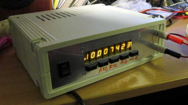
We all know that the Linux kernel has some interesting cruft in it, but did you know that it can actually alert you to the fact that your printer is aflame? We didn’t either until Editor-in-Chief Mike Szczys shared this reddit post that details the kernel function lp_check_status and how it assumes the worst if it detects the printer is online but also in “check mode.” The Wikipedia entry on the “lp0 on fire” error message has some interesting history that details how it’s not as implausible as it might seem for a printer, especially one in the early 1970s, to burst into flames under the right conditions. A toner fuser bar running amok on a modern laser printer is one thing, but imagine a printer with a fusing oven running out of control.
And finally, because 2020 is apparently the gift that can’t stop giving, at least in the weirdness department, the US Department of Defense let it slip that the office charged with investigating unidentified aerial phenomena is not quite as disbanded as they once said it was. Reported to have been defunded in 2017, the Advanced Aerospace Threat Identification Program actually appears to live on, as the Unidentified Aerial Phenomena Task Force, operating out of the Office of Naval Intelligence. Their purpose is ostensibly to study things like the Navy videos of high-speed craft out-maneuvering fighter jets, but there are whispers from former members of the task force that “objects of undetermined origin have crashed on earth with materials retrieved for study.” All this could just be a strategic misdirection, of course, but given everything else that has happened this year, we’re prepared to believe just about anything.