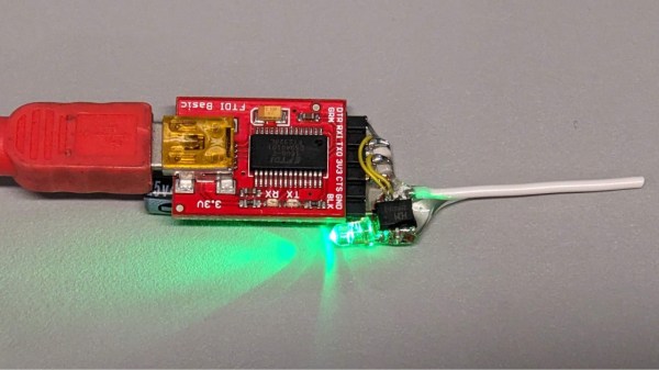
Hackaday alum [Adam Harris] hacked an FTDI cable to use for programming his Arduino. After cracking open the plastic case he found the FTDI chip used is the same as the one in the SparkFun programmer. The only real difference was that his cable wasn’t resetting the Arduino, he had to do that manually. The solution was to reroute the RTS wire so that it connected up to the DTR pin. This proved difficult because of the tiny footprint of the chip, but after many tries he managed to get a piece of wire wrap soldered in place.
Today the parallel printer port is on the brink of extinction (and good riddance, some would say). Largely rendered obsolete by USB, few (if any) new peripherals even include a parallel connector, and today’s shrinking computers — nettops, netbooks, media center PCs — wouldn’t have space for it anyway. That’s great for tidy desks, but not so good if you enjoyed the dirt-cheap hacks that the legacy parallel port made possible.
Fear not, for there’s a viable USB alternative that can resurrect many of these classic hacks! And if you’ve done much work with Arduino, there’s a good chance it’s already lurking in your parts drawer.
If predictions hold steady, nearly half of the United States will be covered in snow by the time this post goes live, with the Northeast potentially getting buried under more than 18 inches. According to the National Weather Service, the “unusually expansive and long-duration winter storm will bring heavy snow from the central U.S. across the Midwest, Ohio Valley, and through the northeastern U.S. for the remainder of the weekend into Monday.” If that sounds like a fun snow day, they go on to clarify that “crippling to locally catastrophic impacts can be expected”, so keep that in mind. Hopefully you didn’t have any travel plans, as CNBC reported that more than 13,000 flights were canceled as of Friday night. If you’re looking to keep up with the latest developments, we recently came across StormWatch (GitHub repo), a slick open source weather dashboard that’s written entirely in HTML. Stay safe out there, hackers.
Speaking of travel, did you hear about Sebastian Heyneman’s Bogus Journey to Davos? The entrepreneur (or “Tech Bro” to use the parlance of our times) was in town to woo investors attending the World Economic Forum, but ended up spending the night in a Swiss jail cell because the authorities thought he might be a spy. Apparently he had brought along a prototype for the anti-fraud device he was hawking, and mistakenly left it laying on a table while he was rubbing shoulders. It was picked up by security guards and found to contain a very spooky ESP32 development board, so naturally he was whisked off for interrogation. A search of his hotel room uncovered more suspicious equipment, including an electric screwdriver and a soldering iron. Imagine if a child had gotten their hands on them?
We’re all used to Bluetooth chips coming in QFN and BGA formats, at a minimum of 30-40 pins, sometimes even a hundred. What about ten pins, with 1.27 mm pitch? [deqing] from Hackaday.io shows us a chip from WCH, CH571K, in what’s essentially a SO-10 package (ESSOP10). This chip has a RISC-V core, requires only three components to run, and can work Bluetooth through a simple wire antenna.
This chip is a RISC-V MCU with a Bluetooth peripheral built in, and comes from the CH57x family of WCH chips that resemble the nRF series we’re all used to. You get a fair few peripherals: UART, SPI, and ADC, and of course, Bluetooth 4 with Low Energy support to communicate with a smart device of your choice. For extra hacker cred, [deqing] deadbugs it, gluing all components and a 2.54 mm header for FTDI comms onto the chip, and shows us a demo using webBluetooth to toggle an LED through a button in the browser.
You need not be afraid of SDKs with this one. There’s Arduino IDE support (currently done through a fork of arduino_core_ch32) and a fair few external tools, including at least two programming tools, one official and one third-party. The chip is under a dollar on LCSC, even less if you buy multiple, so it’s worth throwing a few into your shopping cart. What could you do with it once received? Well, you could retrofit your smoke alarms with Bluetooth, create your own tire pressure monitors, or just build a smartphone-connected business card!
The project was a custom driver for the XVX S-K80 mechanical keyboard, aiming to flash LED patterns across the key LEDs and perhaps send custom images to the integrated LCD. When doing this sort of work, the first thing you need is the documentation of the communications protocols. Obviously, this was not an option with a closed-source project, so the next best thing is to spy on the existing Windows drivers and see how they worked. Using Wireshark to monitor the USB traffic whilst twiddling with the colour settings, it was clear that communications were purely over HID messages, simplifying subsequent analysis. Next, they used x32dbg (now x64dbg, but whatever) to attach to the existing driver process and trap a few interesting Windows system calls. After reading around the Windows API, a few candidate functions were identified and trapped. This gave them enough information to begin writing code to reproduce this behaviour. Then things got a bit odd.
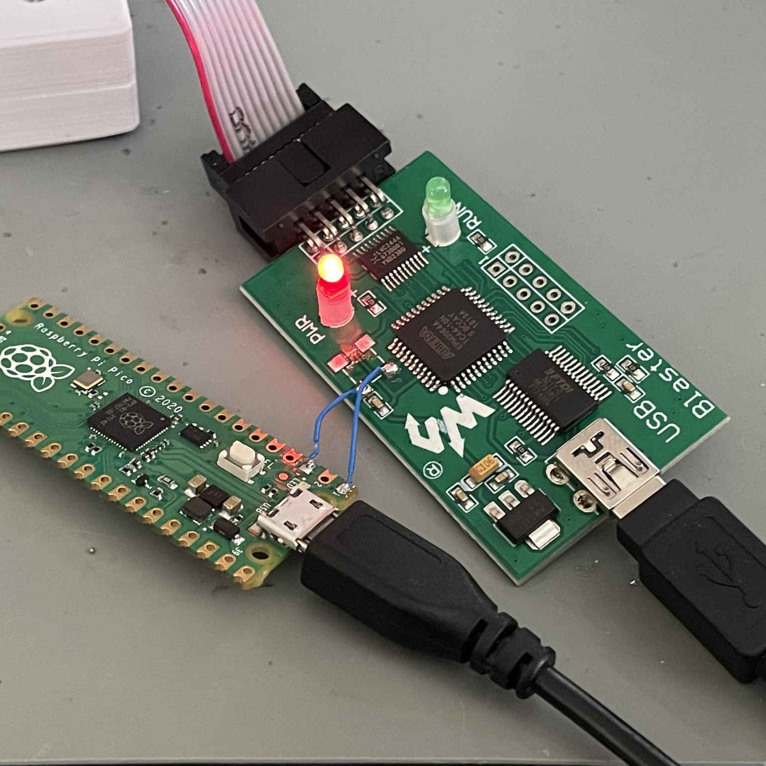
Using an external MCU as a crude clock source for the Altera CPLD. (Credit: [Doug Brown])One exciting feature of hardware development involving MCUs and FPGAs is that you all too often need specific tools to program them, with [Doug Brown] suffering a price tag aneurysm after checking the cost of an official Altera/Intel USB Blaster (yours for $300) to program a MAX 10 FPGA device with. This led him naturally down the path of exploring alternatives, with the $69 Terasic version rejected for ‘being too expensive’ and opting instead for the Waveshare USB Blaster V2, at a regretful $34. The amazing feature of this USB Blaster clone is that while it works perfectly fine under Windows, it works at most intermittently under Linux.
This led [Doug] down the path of reverse-engineering and diagnosing the problem, ultimately throwing in the towel and downclocking the Altera CPLD inside the adapter after finding that it was running a smidge faster than the usual 6 MHz. This was accomplished initially by wiring in an external MCU as a crude (and inaccurate) clock source, but will be replaced with a 12 MHz oscillator later on. Exactly why the problem only exists on Linux and not on Windows will remain a mystery, with Waveshare support also being clueless.
Undeterred, [Doug] then gambled on a $9 USB Blaster clone (pictured above), which turned out to be not only completely non-functional, but also caused an instant BSOD on Windows, presumably due to the faked FTDI USB functionality tripping up the Windows FTDI driver. This got fixed by flashing custom firmware by [Vladimir Duan] to the WCH CH552G-based board after some modifications shared in a project fork. This variety of clone adapters can have a range of MCUs inside, ranging from this WCH one to STM32 and PIC MCUs, with very similar labels on the case. While cracking one open we had lying around, we found a PIC18 inside, but if you end up with a CH552G-based one, this would appear to fully fix it. Which isn’t bad for the merest fraction of the official adapter.
We’ve been keeping an eye on the Framework laptop over the past two years – back in 2021, they announced a vision for a repairable and hacker-friendly laptop based on the x86 architecture. They’re not claiming to be either open-source or libre hardware, but despite that, they have very much delivered on repairability and fostered a hacker community around the laptop, while sticking to pretty ambitious standards for building upgradable hardware that lasts.
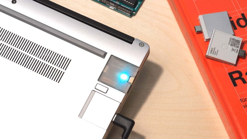
I’ve long had a passion for laptop hardware, and when Hackaday covered Framework announcing the motherboards-for-makers program, I submitted my application, then dove into the ecosystem and started poking at the hardware internals every now and then. A year has passed since then, and I’ve been using a Framework as a daily driver, reading the forums on the regular, hanging out in the Discord server, and even developed a few Framework accessories along the way. I’d like to talk about what I’ve seen unfold in this ecosystem, both from Framework and the hackers that joined their effort, because I feel like we have something to learn from it.
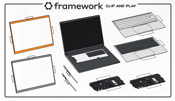
If you have a hacker mindset, you might be wondering – just how much is there to hack on? And, if you have a business mindset, you might be wondering – how much can a consumer-oriented tech company achieve by creating a hacker-friendly environment? Today, I’d like to give you some insights and show cool things I’ve seen happen as an involved observer, as well as highlight the path that Framework is embarking upon with its new Framework 16.