Driving A 16×2 LCD With Voltage Modulation

The basic 16×2 LCD is an extremely popular component that we’ve seen used in more projects than we could possibly count. Part of that is because modern microcontrollers make it so easy to work with; if you’ve got an I2C variant of the display, it only takes four wires to drive it. That puts printing a line of text on one of these LCDs a step or two above blinking an LED on a digital pin on the hierarchy of beginner’s electronics projects.

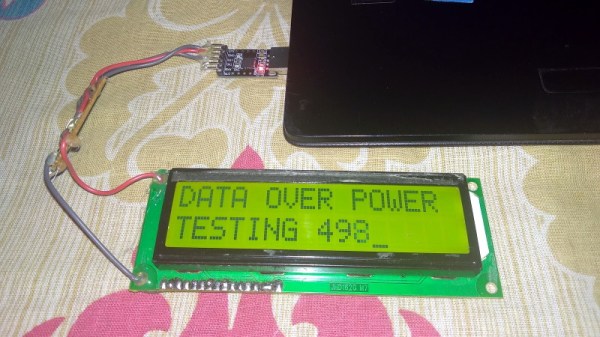
What’s that? Even four wires is too many? In that case, you might be interested in this hack from [Vinod] which shows how you can drive the classic 16×2 with data and power on the same pair of wires. You’ll still need a microcontroller “backpack” for the LCD to interpret the modulated voltage, but if you’ve got an application for a simple remote display, this is definitely worth checking out.

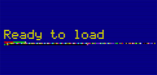
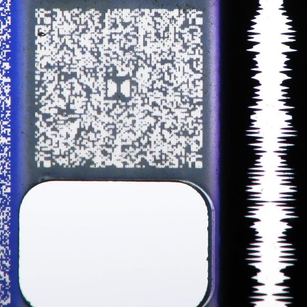
The basic idea is to “blink” the 5 V line so quick that a capacitor on the LCD side can float the electronics over the dips in voltage. As long as one of the pins of the microcontroller is connected to the 5 V line before the capacitor, it will be able to pick up when the line goes low. With a high enough data rate and a large enough capacitor as a buffer, you’re well on the way to encoding your data to be displayed.

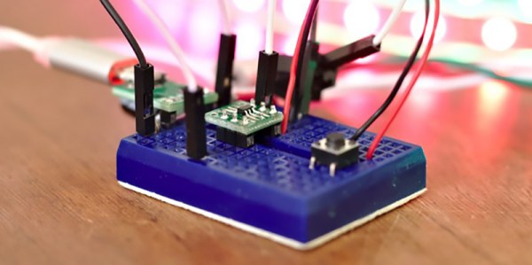
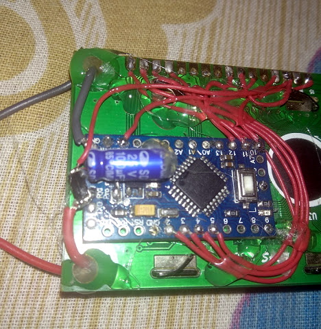
For the transmitting side, [Vinod] is using a Python script on his computer that’s sending out the text for the LCD over a standard USB to UART converter. That’s fed into a small circuit put together on a scrap of perfboard that triggers a MOSFET off of the UART TX line.

We actually covered the theory behind this technique years ago, but it’s always interesting to see somebody put together a real-world example. There might not be too many practical uses for this trick in the era of dirt-cheap microcontrollers bristling with I/O, but it might make a fun gag at your hackerspace.

Continue reading “Driving A 16×2 LCD With Voltage Modulation”

Junkbox MIDI

Do you ever peer into the void…of your hardware scrap box? It may be a wonderland of parts with near-infinite potential, and they just need to be assembled and depending on what you hoard, programmed. Access to a laser engraver doesn’t hurt either. The stuff in [Mr. Sobolak]’s bin is cooler than average, at least by Hackaday writer standards. His sound palette project is a wild mixture of interfaces, hardware, channels, and color. There are arcade pushbuttons, slider potentiometers, rotary potentiometers, miniature laser harp, touch piano, and drum pads which earns the title of junk box build extraordinaire.

Under the hood, we find the usual copper tape, wire and solder connecting operators to a Teensy 3.2. In the more esoteric part of the BOM, we find some fancy SoftPots which look like great fun to play. All the code is linked in the Instructable, but there is absolutely no reason to make an exact copy. MIDI is from the 80s and libraries abound for this protocol so the building may be the hardest part of making an interface that fits your character. Some of the techniques in the Instructable may help you, like how to connect a piezo element so it can read something lighter than a wrecking ball or the laser harp roughly the size of your palm.

We are not short of MIDI interfaces if you are thinking of making your own or be truly random.

Continue reading “Junkbox MIDI”

SNES Mode 7 Gets An HD Upgrade

Emulating SNES games hits us right in the nostalgic feels, but playing SNES games on an 1920×1080 monitor is a painful reminder of the limitations of SNES hardware. [DerKoun] felt the same consternation, and decided to do something about it. He realized that some SNES games have much higher resolution textures that weren’t being taken advantage of. The SNES had a revolutionary video mode, mode 7, that allowed a game to set a relatively high resolution background, and then rotate and scale that background during gameplay.

This pseudo 3d effect was amazing for its time, but taking a high resolution image and squashing it into a 320 by 240 pixel viewport makes for some painful artefacts. This is where [DerKoun]’s hack comes in. He wrote a modification to the bsnes emulator, allowing those rotations and scaling to happen in full resolution, vastly improving the visuals of mode 7 games.

The latest teaser for what’s to come is shown above, mapping the mode 7 backgrounds onto a widescreen viewport, as well as HD.

Come back after the break for some mind blowing SNES HD PilotWings action!

Update: Development discussion has continued in a new thread. Start with link above to get origin story and continue to the new dev thread for recent updates.
Continue reading “SNES Mode 7 Gets An HD Upgrade”

The No-CPU Computer Gets A C Compiler

C is the most perfect language and it will run on anything. It will even run on a computer without a CPU.

The computer in question here is the Gigatron, a fully-functional ‘home computer’ the likes of which you would find in the late 70s and early 80s, complete with a VGA output. What makes the Gigatron exceptional is the fact that there is no microprocessor; everything is just a RAM, a ROM, and a bunch of logic chips. There is no ALU chip. Or rather, there is; it’s just that an entire RISC CPU is implemented in basic logic chips and a whole lot of microcode on the ROM. It’s weird, yes, but it is cool. We’ve taken a look at the Gigatron before, and with this computer you get a glimpse of how clever engineers could have been if there were massive memories available in the late 70s.

While the Gigatron can be programmed in BASIC, the limiting factor of this computer is the fact that it remains exceptionally difficult to program. This is what the 8-Bit Guy says, and even though you can write some simple programs, it’s nothing compared to the likes of an Apple II or C64. If only there were a proper IDE, indeed if only there were a C compiler. That’s where [pgavlin] comes in. He has the LCC compiler working on the Gigatron. This is technically a C compiler for a computer without a CPU, or a computer that is entirely CPU. Either way you look at it, this is impressive.

As far as examples and demos go, [pgavlin] has a demo of Conway’s Game of Life working, and a program that will put dots on the screen. It’s not much, and it’s very slow, but check out the video below.

This isn’t a complete implementation of C, as multiplication, division, mod, and arbitrary shifts left or right haven’t been written yet. Floating point support will probably never be completed, and there’s no shame in that. The hardware is limited due to the fact of the fragmented memory map, but this can be improved by upgrading the Gigatron to a 64k memory model.


Continue reading “The No-CPU Computer Gets A C Compiler”

Making A Three Cent Microcontroller Useful

The Padauk PMS150C is a terrible microcontroller. There are only six pins, there’s only one kiloword of Flash, 64 bytes of RAM, and it doesn’t do multiplication. You can only write code to this chip once, and the IDE uses 8-bit ints. [Anders] got his hands on some of these chips and decided to do something useful with them. It turns out that you can do a lot with minimal hardware, such as driving 300 RGB LEDs with a three cent microcontroller.

There’s some work trying to make an Open Source toolchain for these chips, but [Anders] decided to just go with the manufacturer IDE and programmer. What to do with a three cent microcontroller, though? Obviously something blinky. [Anders] connected this microcontroller to a strip of Neopixels, or WS2812Bs, but instead of driving them by giving each pixel a few bytes of RAM, the entire strip is being bitbanged one bit at a time. It’s some clever code, and even if [Anders] won’t be able to send images to a gigantic graphic display made of Neopixels, it’s still a neat trick.

At three cents and nearly zero associated hardware, this is the cheapest microcontroller we’ve ever seen. Even the minimalist PIC and AVR parts are on the orders of dozens of cents per part, and they still only have the functionality of this three-cent part. The manufacturer’s page has more details on the microcontroller itself including the data sheet, and you can check out the sizzle reel of this project below.

Continue reading “Making A Three Cent Microcontroller Useful”

A Chandelier Guaranteed To Make Some Retro Game Hardware Collectors Wince

If there’s one thing our community is good at, it’s re-imagining redundant old hardware, particularly in the field of classic gaming consoles and their peripherals. Dead consoles have become new ones, Powergloves have ventured into virtual reality, and light guns, well, they’ve become novelty light fittings.

The [JJGames] Nintendo light gun chandelier will probably make collectors wince who prefer their retro hardware pristine, but it’s certainly an eye-catching conversation piece. The twelve guns are carefully disassembled and the Nintendo electronics removed, before a bulb holder and teardrop lamp is installed. Wiring is completed with twist caps,  the guns are joined at the grip with some metal strips and glue, and a chain for ceiling attachment completes the ensemble. A dozen pieces of ireplacable retro hardware sacrificed for a novelty, or a masterpiece of interior decoration? You decide, though we’d opt for the latter in the context of the retro games based business in which it sits.

Our favourite NES lightgun hack ever has to be [Seb Lee-Delisle]’s one that fires a real laser. Meanwhile [JJGames] have made it here before in a similarly wanton use of classic Nintendo plastic, with their urinal made from SNES cartridges.

Resistance Is Futile, You Want This LED Cube

We’re suckers for a good desk toy here at Hackaday, so this 2019 Hackaday Prize entry from [Jack Flynn] certainly caught our eye. The idea is that by using professionally manufactured dual layer PCBs and only surface mount components, you can create a cube that has an LED matrix on each face and all of the electronics hidden within. We’re not entirely sure if there’s any practical application for such a device, but we know we’d certainly like to have one blinking madly away on our shelf regardless.

Before having any of the PCBs manufactured, [Jack] is putting a considerable amount of thought into the design so he doesn’t end up painting himself info a corner (which is of course eight times as bad when you’re building a cube). By importing the PCB files into OnShape, he’s able to “assemble” a virtual representation of the final product to better understand how everything will fit together. He wants to limit the amount of times the cube will need to be pulled apart, so everything from how it will sit in its 3D printed cradle to the placement of breakaway tabs that ensure the internal power switch is accessible are being carefully planned out.

The current design puts the “brains” on the bottom board, with every other panel holding a daisy-chained MAX7219 to drive its own individual 64 LED matrix. Initially the dimensions of the ATmega328p powered cube will be 42 x 42 x 42 mm, with a total of 384 LEDs. Ultimately, [Jack] hopes the modular nature of the design could allow the size of the cube to be increased, or perhaps even take on a different shape entirely.

Generally the LED cubes we see are of the more wiry variety, so it’s particularly interesting when they take on solid forms like this one. Given the nearly universal popularity of blinking LED gadgets, we think this particular project is well positioned to make the leap from one-off hack to a commercial product.

Continue reading “Resistance Is Futile, You Want This LED Cube”